|
|
Post by Andrew Rowland on Jul 17, 2014 2:12:48 GMT -5
The assembly nearing completion.... 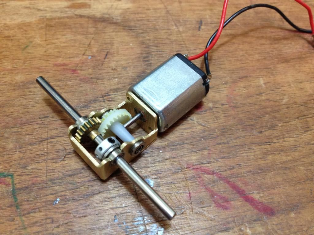 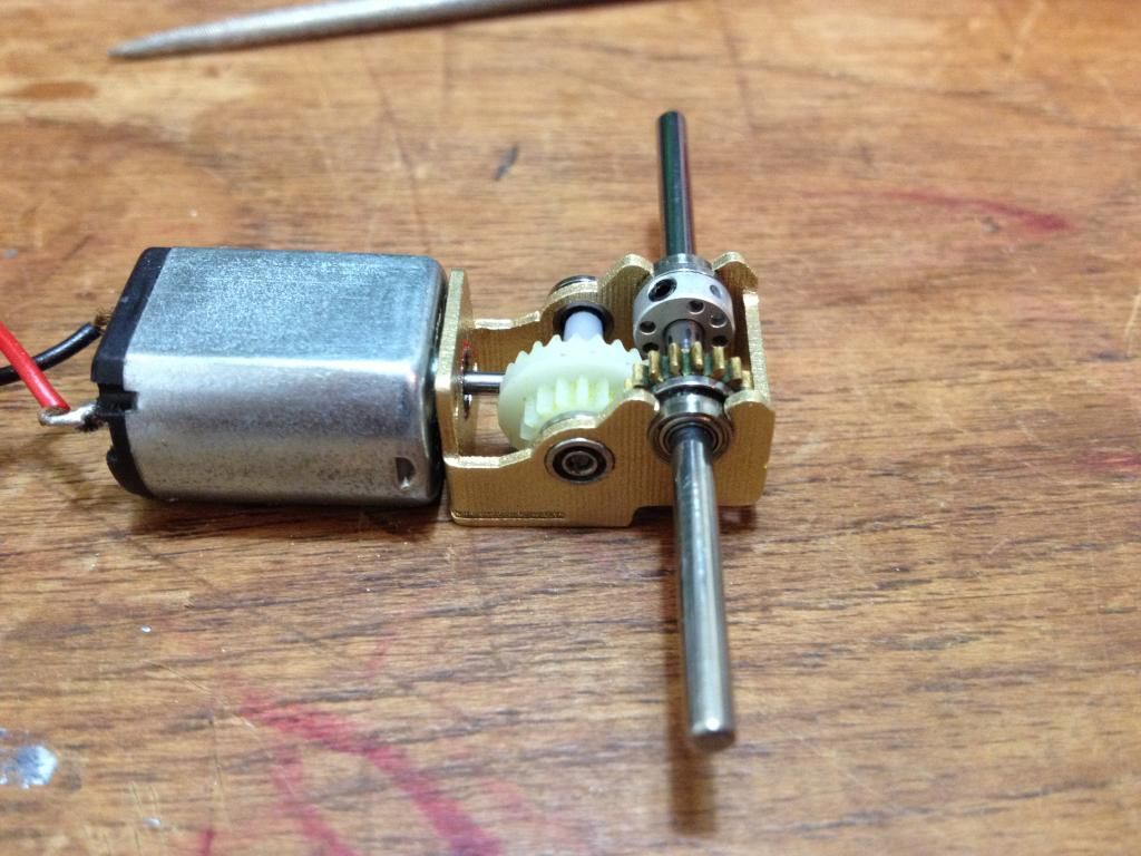 |
|
|
|
Post by Mark Huber on Jul 17, 2014 16:42:21 GMT -5
Whoa..
Tight tolerances eh? It may just be the photo, but it appear there's only about a hair's breadth between the back plate of the bracket and the gear.
Is that bracket one piece, two pieces? more?
|
|
|
|
Post by Andrew Rowland on Sept 1, 2014 16:04:18 GMT -5
|
|
|
|
Post by Andrew Rowland on Sept 3, 2014 14:22:17 GMT -5
|
|
|
|
Post by Aurora on Sept 5, 2014 11:08:12 GMT -5
That's very tidy Andi. What is the principle of function behind this design?
|
|
|
|
Post by Andrew Rowland on Sept 29, 2014 2:15:16 GMT -5
Having tested the car on George Turner's track and found it works well i've decided to build the plastic crown gear element in bronze to ensure it can deal with the rigours of a long proxy series. The gear shown above is still a plastic prototype designed to push the Policar Lotus which only weighs 55g. This heavier scratchbuild will need something beefier! So i'm combining a Wizzard 25t crown with a 1.5mm bore with a Policar straight cut gear with 3/32 bore. In the absence of any real machinery I bolted through the centre of the crown and held that in my dremel. Then filed away the hub to 3/32 and pushed the gear on. The gear similarly had a shelf filed off. 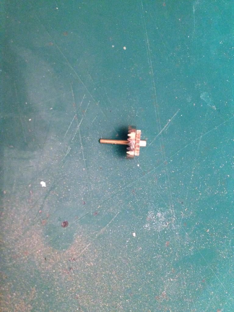 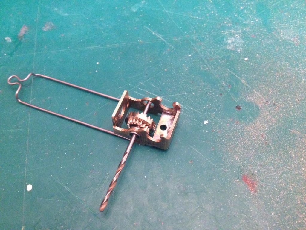 The body is also evolving... 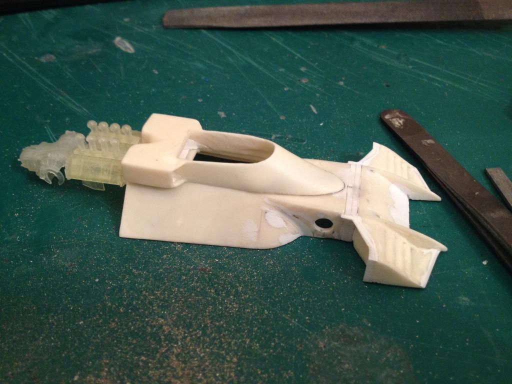 |
|
|
|
Post by Andrew Rowland on Oct 19, 2014 14:13:18 GMT -5
I've been making some progress today. Its the first free modelling day i've had for literally years so its been great to really move this build forward.... I started by building up the air box out of plastic sheet and some odd bits of resin from the kit airbox which was discarded. I wanted to use the airbox as the object that took the beating during a big off given this car needs to do a full season without maintenance. So there is a brass pin fixing it to the engine block and another in the front whihc fixes to the rollover bar and the top of the body. All hopefully not that obvious once its complete..... 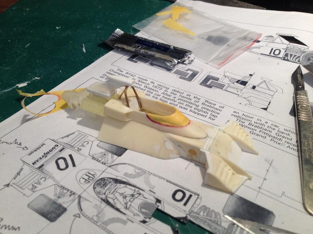 The windscreen was also marked out and masked off to check the proportion. The masking tape was then carefully removed and set aside as a potential future template. This shot shows how the scalpel line is highlighted with a bit of red ink. 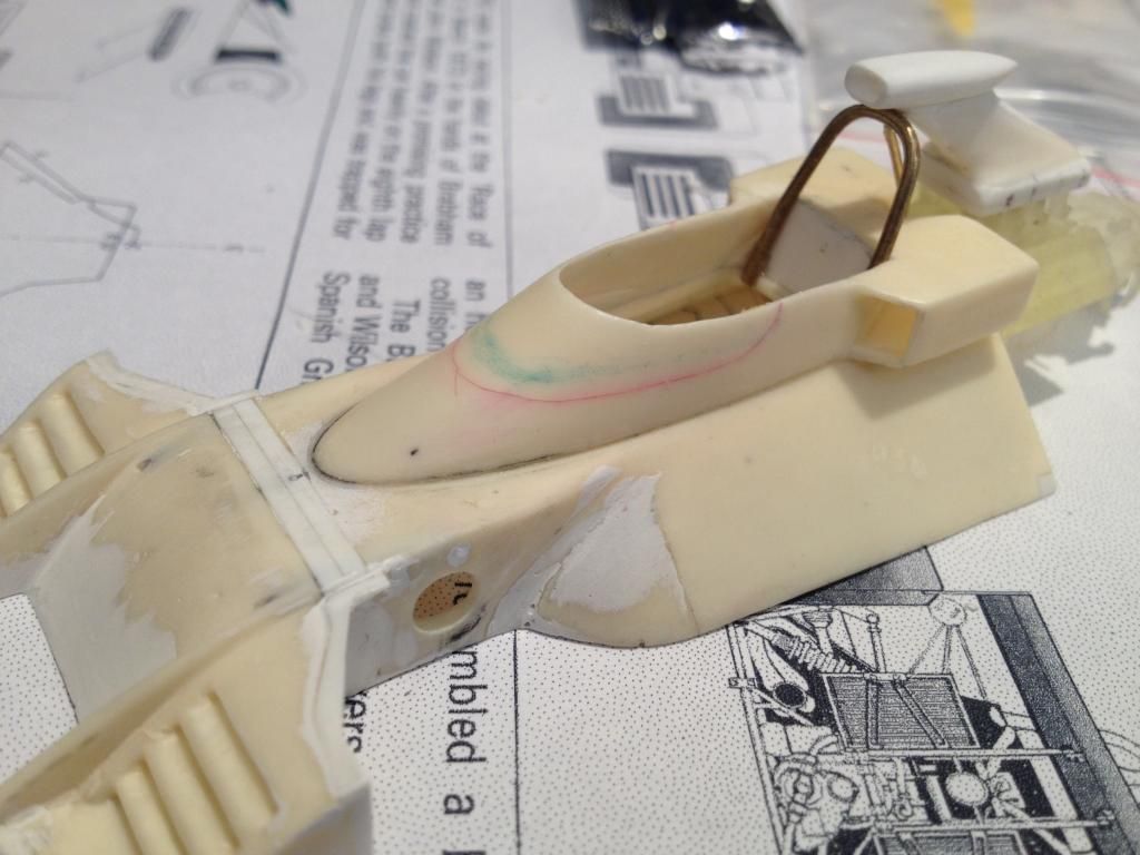 I cut the screen off with a scalpel. 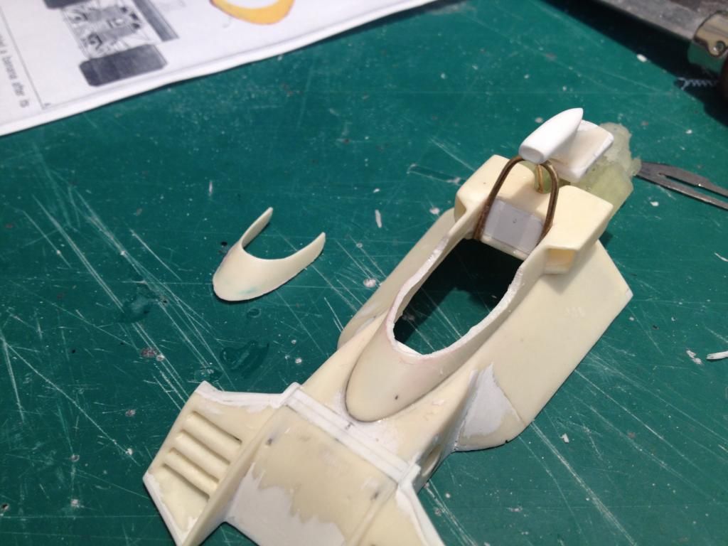 The rear of the car begins to take shape. Constant checks are made to the drawings to ensure accuracy. I tried using photocopies but they distorted things in one direction by 1mm. 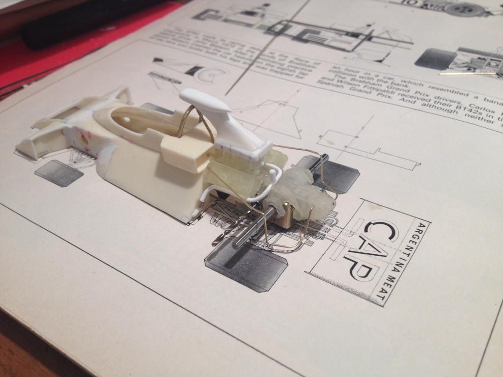 This is as far as I have got for today. Lots done but still so much to do!! 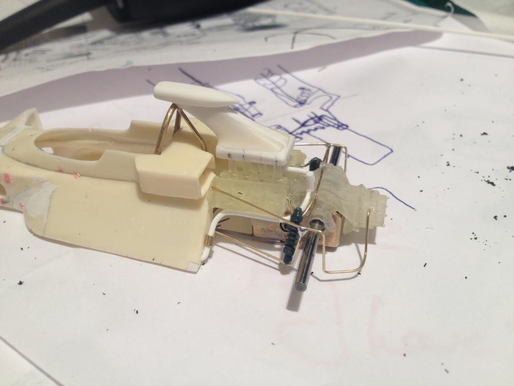 I think the exhausts will be the next thing. |
|
|
|
Post by Andrew Rowland on Oct 27, 2014 16:37:20 GMT -5
A little more progress: The front suspension is in (minus the damper and spring) and the exhausts are also done (not quite as symmetrically as i'd have liked but hey!) 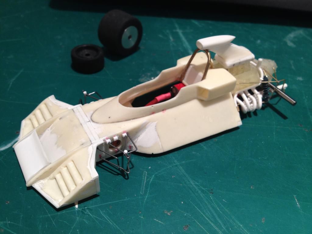 Overall its coming on and sits fairly comfortably. I'm running in the gearbox tonight so soon we'll have a full working car for a little testing prior to painting and finishing..... 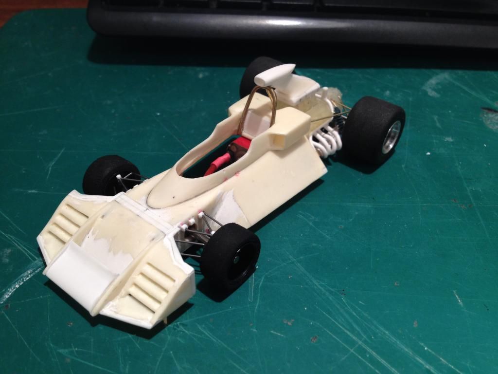 |
|
|
|
Post by David Mitcham on Oct 28, 2014 2:42:00 GMT -5
Hi Andi
The Brabham looks terrific. The suspension detail is a work of art and the exhausts look just right to me. If it goes as well as it looks - which I have no doubt it will - I'm sure it will set the benchmark for the rest of us live up to. It would be good to see the progress on some of the other builds apart from yours and Mark's.
Best Regards
David
|
|
|
|
Post by Andrew Rowland on Oct 31, 2014 18:02:41 GMT -5
I'm trying to keep the pace up on this build as time seems to be shortening for the start of next year's series! I decided very early on that the rear wing would be supported off a scale assembly soldered in brass and fixed direct to the gearbox as the original would have been: 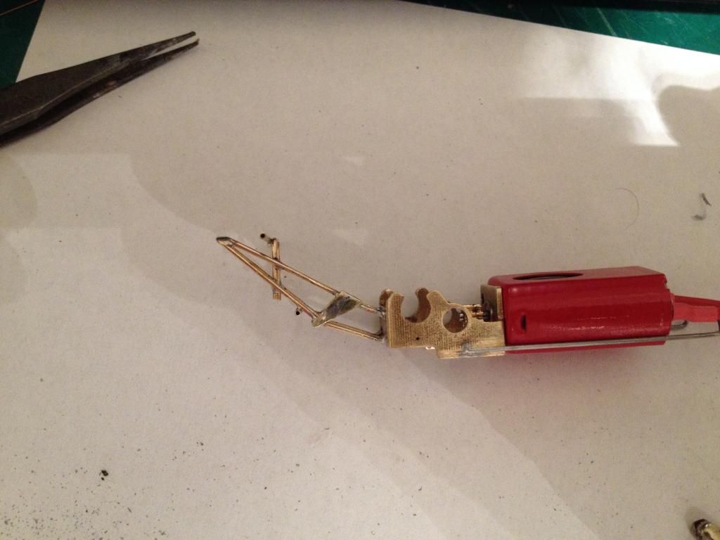 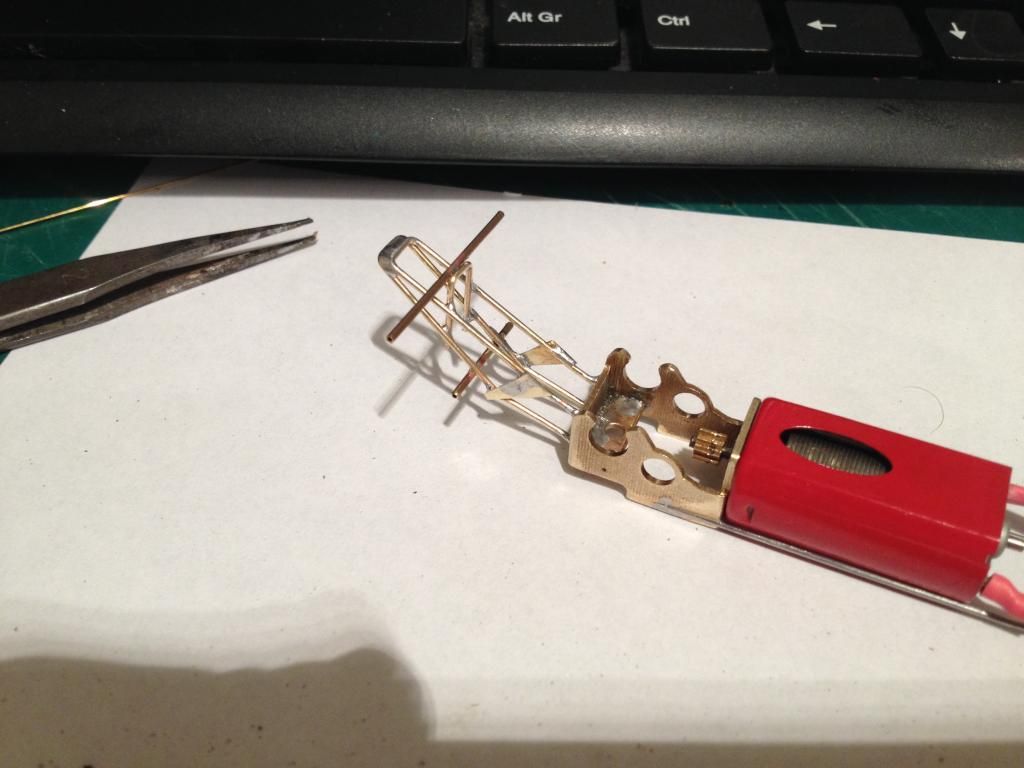 The benefit for me is that the wing will be acting steadily direct on the rear axles, rather than through the flexibly mounted body..... |
|
|
|
Post by f143 on Oct 31, 2014 20:33:04 GMT -5
Hi Andi, lovely work on the construction of both the body and chassis of the Brabham.
Would you be able to describe how you bend, hold and solder the parts with out disturbing other soldered joints on the pieces please?
Thanks
Nigel
|
|
|
|
Post by Andrew Rowland on Nov 1, 2014 12:22:50 GMT -5
Hi Nigel, thanks.
Unfortunately I didn't take any build shots so i'll only be able to describe in words.
First I always start with a very clear drawing, at least in one direction. With the dimensions in the other. Then I start to sketch out roughly which parts might be bent out of a single piece. The idea is to have as few soldered joints as possible and to make as strong a structure as possible.
So I had a side view drawn out and simply bent a piece of 0.8mm dia. Brass bar round to make one of the main frames, in this case I did the bottom one then the top. For brass i use smooth teeth pliers or, if I want curves a pair of round teeth pliers.
The first frame I superglued to the paper drawing standing up vertical. Then I glued the second one similarly so they just touched at the long 'top' joint. No glue anywhere near the part to be soldered.
With that I soldered the two together. For this size of work I use a 25W soldering iron which is about 60 years old..... My dad's in fact.
Next came the 'c' shaped piece that fixes the four main bars together. Here I made the piece just over width so it was a push fit and held itself in. No other means to hold. Hold the soldering iron on the part glued down to the paper and the heat transfers to the other part and then offer up the solder to the joint. Touch the solder against the iron to get it melting and running into the joint. Before soldering clip a crocodile clip onto the already soldered joint (the closest one) as a heat sink so that it won't un solder.
Then the rest of the bits get added up to the point when the whole thing has to be cut off the paper. From there you need to find ways to keep the pieces steady as you solder them and use crocodile clips to keep already soldered joints from desoldering. This can get complex but is usually no real big deal.
Eventually you get the thing built up as required.
Don't worry if too much solder goes on, just file and sand it down after.... Of course the less you use is better but really don't worry it can always be taken off later.....
Hope that helps
Andi
|
|
|
|
Post by Andrew Rowland on Nov 1, 2014 16:39:24 GMT -5
Been working on the rear wing and thought people might benefit frim seeing my method of building a well attached, string but perfectly finished aerofoil. First the top plane is filed and hand bent to give the correct profile. Then it gets glued onto the support structure with the metal cross bar. 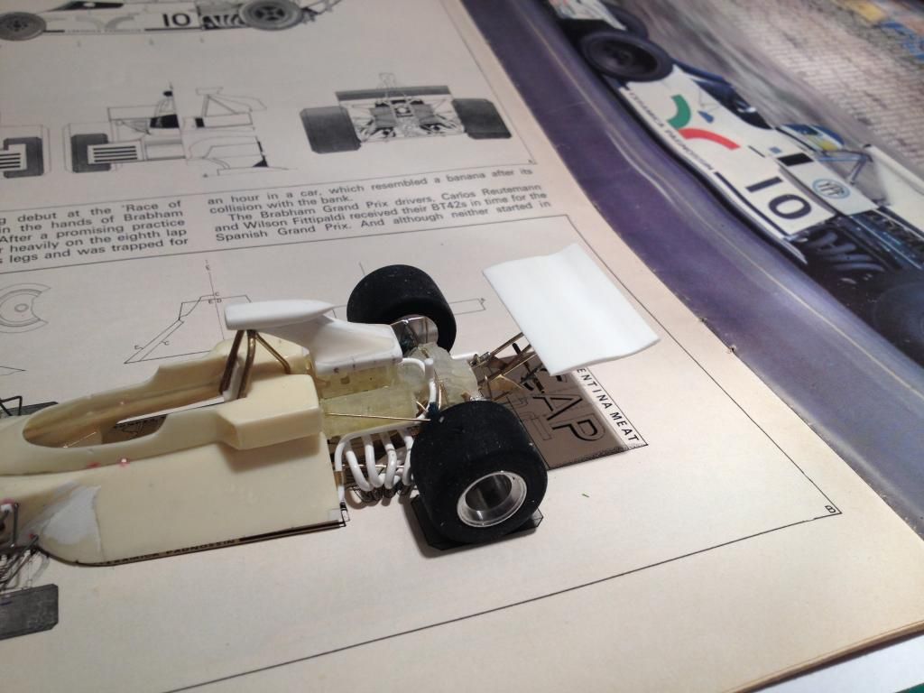 Working over the scale plan. 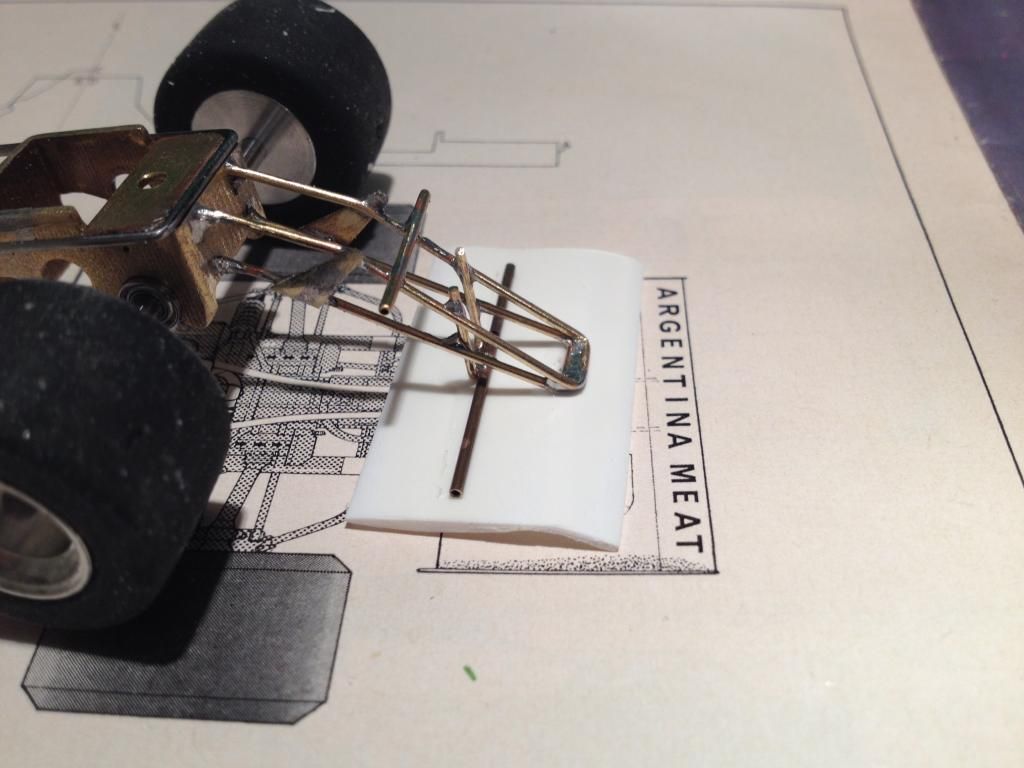 The underside is another plate with strips cut out so it can slide on but remain very strong once glued on. 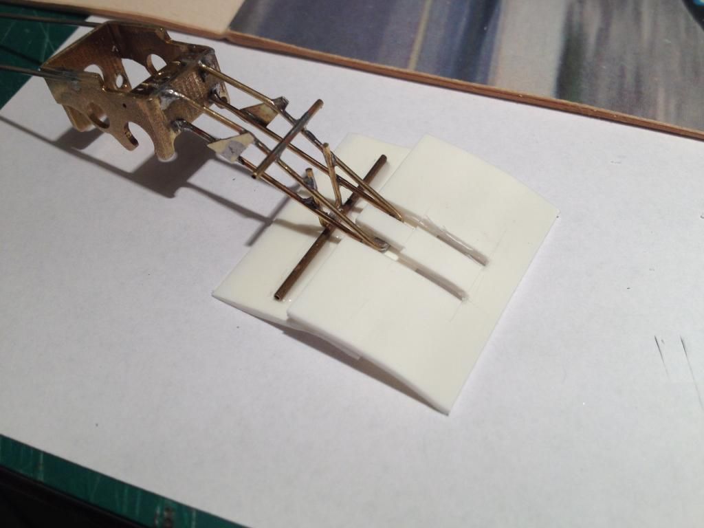 This is then glued to the metal support structure underneath and then front and back. 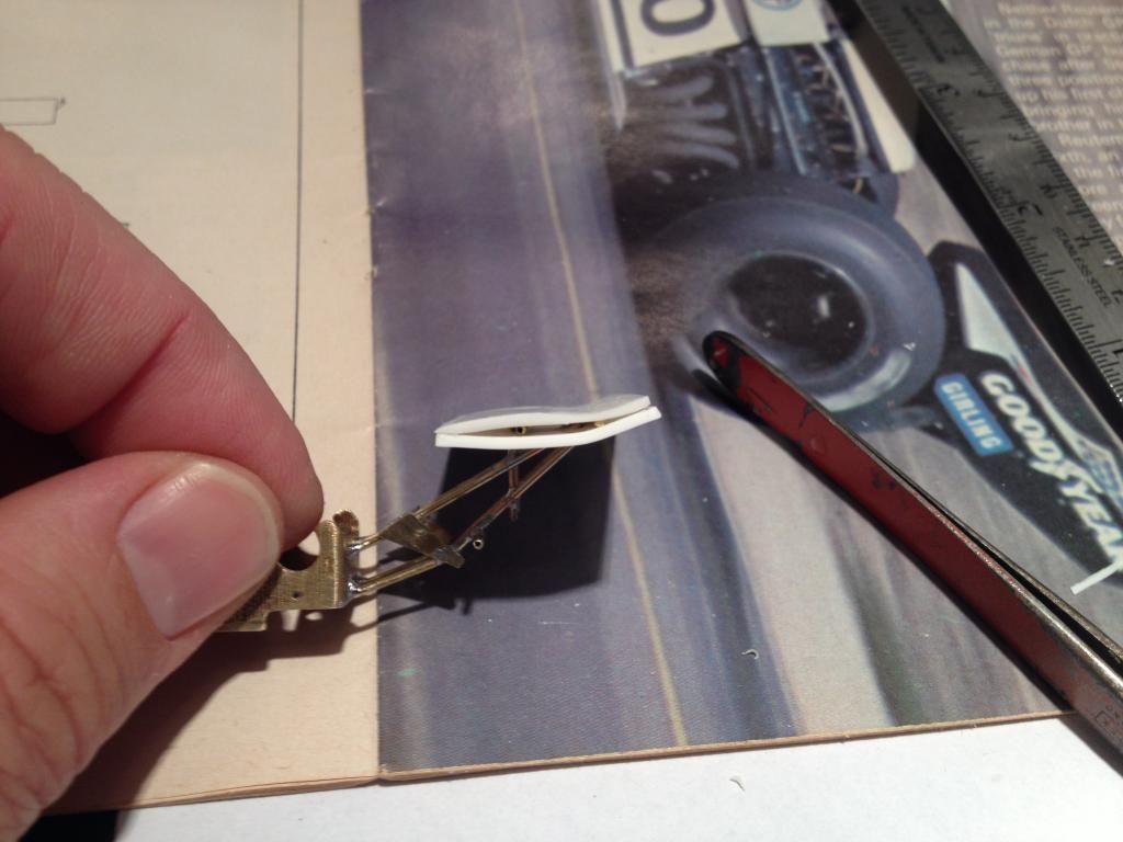 Strips close the holes and the whole thing gets filed and sanded. 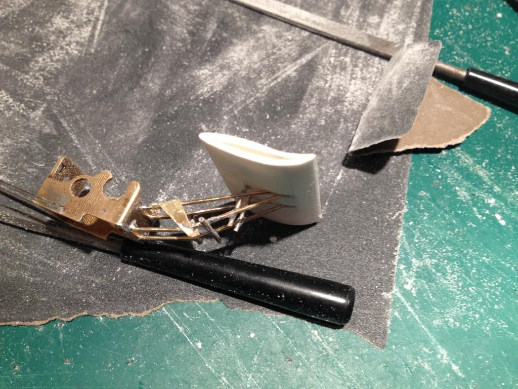 Hope that's useful Andi |
|
|
|
Post by David Mitcham on Nov 1, 2014 17:05:49 GMT -5
hi Andi
That's really helpful as I need to turn my mind to building the Tecno wing supports and wing (although I may use the BSB supplied one).
Mark, take note - wings are easy!
Best Regards
David
|
|
|
|
Post by Andrew Rowland on Nov 4, 2014 4:04:55 GMT -5
The car assembled, now painting.... 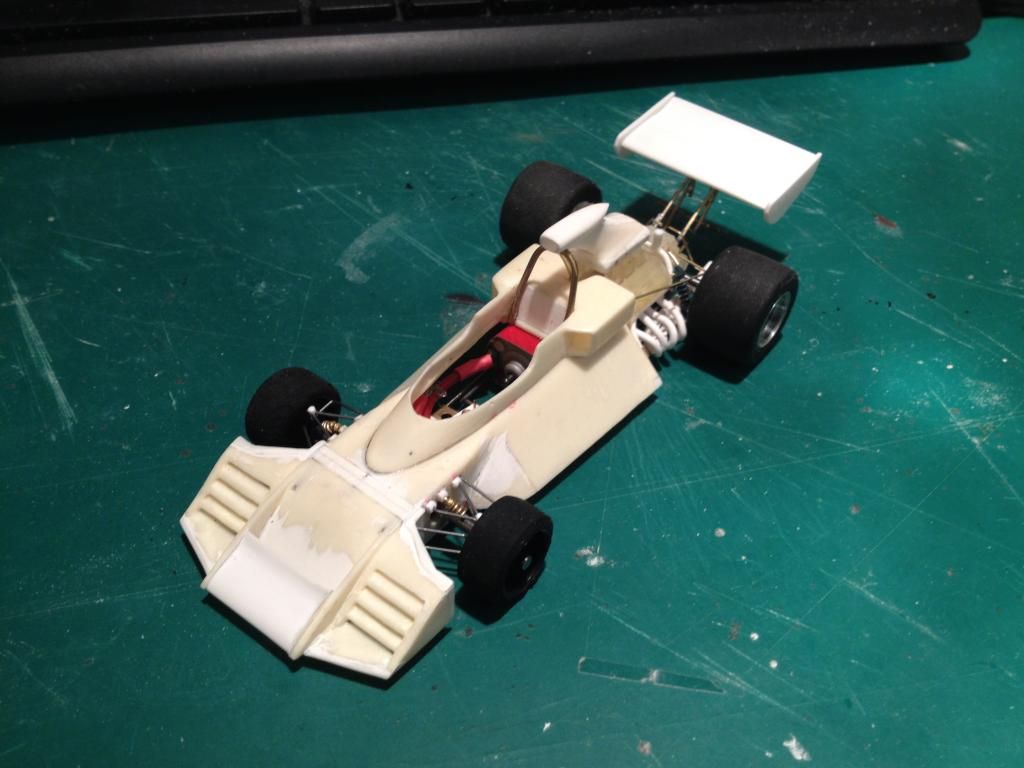 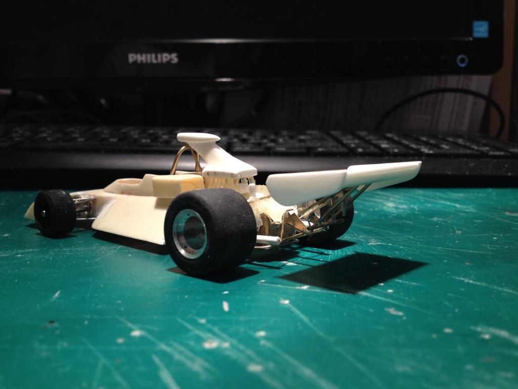 |
|