|
|
Post by Chris Wright on Dec 19, 2014 0:16:10 GMT -5
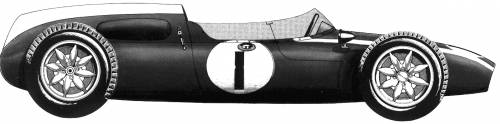   Rosco, these are the only drawings I could find of a T-53 so far, I hope they help. Try this site for a couple of unseen T-53's: www.bonhams.com/auctions/14261/lot/221/Now you could help me, please there is no such word as sodder, it's not a word that's in any dictionary, please use the correct word Solder. (even though most Americans "say" sodder.) Chris |
|
|
|
Post by Phil Kalbfell on Dec 19, 2014 5:51:21 GMT -5
Jim Palmer and Red Dawson ran T53' in the Tasman Series,
Palmers was white with Green stripe I think.
|
|
|
|
Post by rosco01 on Dec 19, 2014 17:40:49 GMT -5
Chris - those pix are exactly the ones I have been searching for. I have been given links to line-drawings including specifications - I'll chase up the other link you posted shortly - but with what I now have and these two beauties, I believe I've got enough to make up an actual size scaled drawing.
Phil, again - thank you. To enter the Tasman Proxy series, I suppose I can now rest comfortable that the model/s I propose will be eligible.. I believe there will be sufficient allowance for poetic license to allow me some margin for accuracy to any one specific car.... undoubtedly, I'll be throwing many posts up over the next 12 months as these models take shape.... not to mention the encapsulated questions...
Chris, request received, noted and granted.... I was not aware that the word is pronounced that way in the US.. so, it now grates less... well, a little less.
I have another trip coming up in the next week back into Melbourne to pick up some more little tools from the jeweler's supply store where I obtained my ceramic soldering tile (see, Chris - conforming already) - and try to get my hands on some thin silver solder - the silver solder I have is general purpose and was purchased from "the big red hammer" store - aka "the big boys toy store" here in Oz....
I also have low melt Bismuth solder which I use when soldering white-metal and white-metal to brass. I don't believe it will withstand the grinding by Dremel of any surrounding areas...
I probably need to find some high temp silver solder - in those video's mentioned, the chap turns his soldering station up to 850 F on a couple of occasions... that's a lot higher than the 220 C melt point the silver solder I currently have.. so, there is probably variants in product - and I'll chase up the jeweler's site to confirm...
If there is a known variant of this silver solder which lends itself perfectly to our needs - I would appreciate any reference, along with direction to procuring it...
Thanks again, Chris and Phil.. we wait.
frats,
Rosco
|
|
|
|
Post by Chris Wright on Dec 19, 2014 17:45:49 GMT -5
Rosco,
If you're picking up Solder supplies the most important is ACID FLUX if you can find it, a must for strong Brass or Steel joints.
|
|
|
|
Post by rosco01 on Dec 19, 2014 18:01:23 GMT -5
Thanks Chris - yes, reference is made of very strict cleanliness and aggressive flux.
A properly tinned tip, clean materials, sufficient flux and correct heating of componentry in unison is what I believe to be the critical elements for satisfactory soldering..
The piano wire componentry of this build is probably the material of greatest issue - I have never soldered it.. but I get the feeling I'm about to learn to...
Brass is an easy one - I do my best soldering with brass. If it's clean, I find that solder flows beautifully ... there's something about brass which both conducts and retains heat - I struggle to understand why some locomotive scratch builders continue to use glues...
White metal (oops, nearly misspelled the word by starting with an "S") is a difficult medium.. solder won't stick to it unless it is brought to a sufficient temperature... and any substantial increase results in the casting turning to a blob....
The trick to white metal is to bring the temperature up quickly at the joint and keep the tip there until the metal begins to just glisten, hit it with the bismuth and get the heck out of there pronto. Larger parts are much easier - as the mass absorbs heat like a heat-sink... it's the little bits (like mirrors, caps, levers etc) which often are supplied in multiple... the manufacturers "know" these are vulnerable to over-temperature abuse.....
I might bang up a pic of one of the loco's I built.. if anyone wants to see how crazy I can go with detail.....
Ok - went right off my own topic with that... blasted fingers!.. I should bind them together with rubber bands.. that would deter me from these lengthy posts....
frats,
Rosco
|
|
|
|
Post by Ember on Dec 26, 2014 20:51:48 GMT -5
Ross, I too was fearful of soldering piano wire. I'd heard so many horror stories. But really, any trepidation I felt was completely without cause. Keep it clean, use an acid flux (i've got old school Baker's Fluid because it was available in town), have patience with your soldering, let the heat do its work and the solder flow, and clean it up with a good alkaline soap afterwards. I know Chris recommends bicarb soda and soap, but I just use soft soap and a soft toothbrush.
I'm sure others will have better recommendations of how to go about things. My point is only that it is easier than you may expect if you approach it right.
|
|
|
|
Post by Phil Kalbfell on Dec 26, 2014 21:47:18 GMT -5
I thought we would have seen some building by now, you have had the bodies two days!
I cut my piano wire to approx lenght and then clean and tin all of the lenght. This stops it from rusting and makes it easier to solder to later.
|
|
|
|
Post by rosco01 on Dec 27, 2014 15:12:58 GMT -5
Thanks, Ember and Phil -
yes, I've done a little work - but not much to show for it yet. I decided to go with the 0.055" piano wire in lieu of the 0.062".
I had a bit of trouble trying to make a 180 degree bend in the thicker wire... so, opted for the slightly finer one.
My bend is not perfectly radiused, but it does come back under both sides of the motor bracket.
I have it lined up on the ceramic board with brass axle bushes interference fitted into it. I have used 3/32" aluminium tube through the bushes and pegged it square to the centre line of the board. I cut the wire so that it has given me plenty to work on for the front.
I am yet to do anything with the bodies, Phil - but have studied them very closely and must congratulate you on your work - thank-you. The wheel inserts and added tyres now give me some indication of the riding height that the chassis will be - but, until the wheels come from RD - I'm a little reluctant to solder anything.
I expect that I can solder the bushes and chassis rails to the bracket, however - the riding height of the rails under the bracket will not change with wheels...
I believe it's the front wheel/guide arrangement which will be critical to have wheels fitted - to get parallel axle heights and position the guide stem/front axle plate and guide tube height set up.
So, sorry to disappoint anyone following my humble attempts at this, my first build... but, I have made a start - and at present am reasonably happy with plans and proceedings....
frats,
Rosco
|
|
|
|
Post by rosco01 on Dec 28, 2014 0:16:02 GMT -5
Ok - finally bit the bullet and spent a couple of hours on the chassis today. Ember - absolutely correct..... clean joints and Baker's, plus a good bit of heat - and my silver solder flowed like silver gold... I did the axle bushes first - deciding (rightly or wrongly)that I'd put the large flange on the inside - so that I could fit spacers between the crown and inside of the bushes... as opposed to running brass tubes outwards from the bracket... if I'm wrong - please tell me, I've stopped for now waiting to do #2 (building two of these up together). First attempt to fit the looped rail around the bracket went extremely well.... until I trial fitted it under the body... loop sat far too far back and fouled the rear of the body.... so, unsolder (that hurt - I thought I had it absolutely smack on). Brought the rails in a bit at the rear of the loop then sent them out to chassis width just after they crossed the rear of the bracket.... it now will clear the body - and still allow some more clearance for body float if I want to gouge out some of the meat.... The axle floats/spins extremely free in the bushes... I did this by aligning them with 3/32" aluminium tubing then soldered them in before adding the rails later.. I had to work the bracket a bit to get the rails to run square with the motor mount face - and square vertically to the axle... I believe I have got it all lined up square in all directions. The bracket needed to be opened out to allow it to sit squarely on the rails - with both of them sitting on the building board. So, folk - here are the first three pix of the project.... I know my joints and soldering won't impress many - but for my first (well, second - if you count the one I "undone") attempt - I'm pretty happy... As mentioned, I don't have the motors or gears yet... but surely, this bracket and rails could be assembled with the bushes soundly soldered in place.... I would strongly encourage any comments please - I have absolutely no idea what I'm doing - and if what I am doing is anywhere near what is needed.... pix... 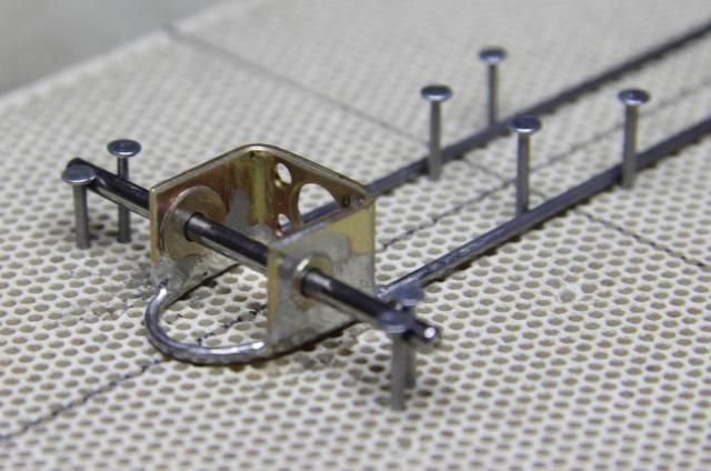 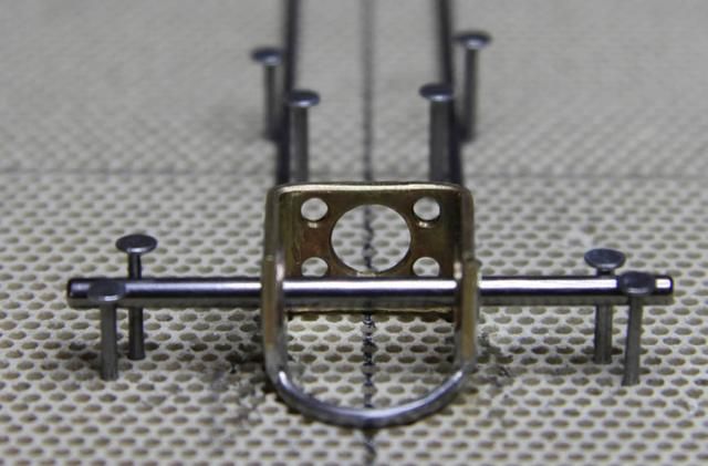 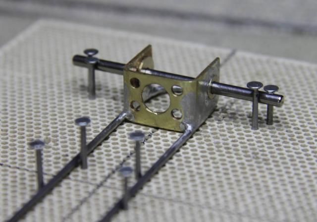 frats, Rosco |
|
|
|
Post by Phil Kalbfell on Dec 28, 2014 8:13:55 GMT -5
Ross with the rails under the bracket they may sit well below te body, before doing much more check the fit under the body.
No need to wait for the wheels, check the rules for minimum tyre diameter, and work to those sizes.
Adding spacers between the gear ang bushes is the best way to go, it is a bit cuddly to do but once setup the gear mesh won't move.
|
|
|
|
Post by rosco01 on Dec 29, 2014 17:08:04 GMT -5
Thanks Phil,
The brackets I have will certainly need shaving at the upper rear corners. I will probably radius them off just leaving sufficient to comfortably retain the bushes.
I understand that the motors are very small - and hope there is sufficient room/clearance. I expect there is, as it will be forward of the bracket and will mainly be positioned in the open cockpit area.... so, guess whoever this driver is going to be - he's on notice for some belt tightening...
I understand your advice on setting the height - with the minimum tyre diameters.. I can centre the axles for this.
I'm not certain how I'm going to go with the front plate yet - I do have some manufactured ones - but I'm more inclined to try something from scratch.
With this body, I don't believe there is any concern with the Slot-It guide being visible from above.
I welcome suggestion on location of the guide bearer tube... is there a "sweet spot" for tuning this location.. i.e. - how far forward of the axle?
I have studied many builds and from what I have seen, most seem to have the guide mounted with the rear 1/3 of it extended rearwards over the axle....
I was of the opinion that having it as far forward as possible might give the model greater cornering.... i.e. longer pendulum with less lateral force..... especially with these narrow little tyres...
I can't think of a downside for doing this - not being a rally car, it does not need the tight cornering ability.... I expect most tracks will be of large radius curves.. perhaps with one or two which are the equivalent of a Scalextric R1......
Unless, there is a tendency for the guide to de-slot if placed too far forward of the front wheels... I suspect there may be a conflict with the turning radius between the guide track and wheel tracks..... maybe that's why most people keep the guide within the two radii of the front wheels....?
I am now of the opinion that I will run free wheeling hubs at the front... I have received a few suggestions on how to achieve this.
I do appreciate that whichever way I go, I will have to solder a retainer at the end of the axle.
When I built my steam loco's - the fitting of wheels to axles was critical.
There needed be just enough clearance for the wheel centres to float against the bushes, but not sufficient that it would cause the loco to go out of gauge on curves.
I was directed to use printer/typing paper... just your standard garden variety A4 80 gsm variety.
By placing a folded over piece of this between the bush and the wheel, then soldering the wheel to the axle - the paper when removed afforded just enough clearance...
This is my plan to solder a retaining washer onto the end of the axle... then fit the wheel inserts....
As for whether I use a 1/16" or 3/32" axle, I am undecided.
I can't go with the hardened steel 3/32" axles I have purchased for the project, but can use 3/32" brass tube with a 1/16" piano wire axle through it. The hubs will be screwed to the tubing, the tubing will run on axle.
I expect that I'll have to fit tubing spacers from the bracket out to the hubs, having soldered the 1/16" axle to the bracket.
Had I anticipated this in the planning stage - I should have ordered 1/16" axle hole wheels in lieu of the 3/32"... I did not originally plan to have free wheeling hubs - but to use the 3/32" axle through 1/8" tubing, the tubing soldered to the bracket and the hubs screwed to the axle....
So, once I am comfortable with the rear bracket fitting into the body with a comfy clearance... I suppose the next step is setting the front plate location and height.
The guide will pivot in brass tubing - I can leave fitting this for now until I have the wheels and tyres.... then solder the guide tube in place through a drilled hole in the bracket allowing for a washer for the guide to bear on.
I have screw held Slot-It guides with a cam-like upper washer. The braid and motor leads are each grub screwed into the guide.
Thanks again, Phil - work continues.....
frats,
Rosco
|
|
|
|
Post by Chris Wright on Dec 29, 2014 19:50:46 GMT -5
Rosco,
I just gotta know.... what does "frats" mean in Australia?
|
|
|
|
Post by rosco01 on Dec 30, 2014 18:20:38 GMT -5
Ok folk,
Little bit more work done - only a report, no pix.
Started work on chassis #2 for the 2nd Cooper - and Ember, I concur - piano wire seems to bend a lot easier and take better shape the second attempt... this one nearly wrapped itself around a vice-held bolt like a divining rod...
The motor bracket - I wasn't so lucky. Of the five I have, I might have picked the odd one - but this one needed a bit of work to straighten..
I spent a few hours in the workshop yesterday making up a set of plates out of 8mm mild steel - so that these brackets could be made square and true - with the motor mount face flat and the sides square and vertical.
The result is such that with the bushes fitted - the axle will spin freely..
When I post a pic of the second chassis after soldering, you will note some small "hammer" dents... I will use a metal block between the hammer and bracket for the remaining three I have.
I also had to file out the two lower corners for the chassis rails to pass through. Maybe I've got this wrong as well, but my understanding/opinion is that the bracket should sit atop the rails - not between them.... information appreciated.
The person who made the brackets did a magnificent job in marking out and drilling the holes - but I have now found that they can be slightly tweaked to bring the three sides to a better result... not by much, but enough to afford free spinning of the axle within the bushes - with these bushes fully home against the sides.... maybe people don't go to these extremes.. maybe I'm just a little bit crazier than I understand my compulsiveness to try and get things right.... I don't know... jury is still out..
Ok - so now, we are about to make up the rear section of chassis #2 - should have pix up by this afternoon.
I am now a bit concerned about mounting the body - I read Ember's question in her thread and am a little unsure as to what is the best/most effective method..
I am considering soldering a small brass plate (very small) within the rear bend of the chassis rail to the rear of the crown (RD yet to arrive). Through this, I will drill a small hole which will afford connection to a post glued to the body.
At the front, the bracket I intend to make up will also have provision for another small hole - and a corresponding post glued to the front of the body.
My motors arrived yesterday from England - I don't know through which countries they traveled, but in some of them - the word "fragile" obviously is beyond their comprehension.... my four motors arrived sliding around in a rather large box for the requirement... the attempt to wrap them in bubble wrap was probably acceptable on dispatch - but on arrival - the motors and bubble wrap were removed singularly....
On three of the motors, the identification has all but rubbed off.. so, I expect that these poor little things have "lived" already... I cannot see any physical damage - but they have indeed "rubbed shoulders" in transit.. I will need confirmation from the series co-ordinator that they are in fact eligible... with only the remnants of the fine black print visible on the bodies.
Ok - off to work - small report and more pix later today.. hopefully.
frats,
Rosco
|
|
|
|
Post by Phil Kalbfell on Dec 30, 2014 18:39:33 GMT -5
Ross depending on what body I was building for I have run the rails on the outside of the bracket, but for narrow bodies I cut 1/16 off the two sides of the bracket so the rails fitted under the sides and the motor between the rails.
As for body mounts, most guys only use a front mount located between the front axle tube and the cockpit. This is sufficient as the axles and suspension will locate the body.
|
|
|
|
Post by rosco01 on Dec 30, 2014 20:22:58 GMT -5
Phew! Phil - that's great news.... I thought I'd missed something, thanks heaps!
I had struggled in my thoughts of the rear mount for the body - and yes, will now follow the general consensus and mount it using a front attachment only....
My suspension (static) design is yet to be planned out - I've got some broad-brush ideas in my mind's eye.. but nothing established yet.... basically a pair of piano wire wishbones and perhaps a brass end washer just before the hub - plus some form of wound fine wire coil spring - this time around, that's probably more than I'm capable of.. I love to add the minute detail that some of the experienced builders on this forum have effected - and also to the level of that with some of the locomotives I have built... but, for these two - I'm probably even a little more adventurous in my plans than I would be advised to entertain..
Thanks again for your guidance, very much appreciated...
a very relieved Rosco, I can assure you... I simply didn't know how I was going to fit a mount base in the very restrictive and narrowing area of the tail of these little models.... I take it, a 9/16" UNC bolt is not required for the front bracket/body mount.... 10 BA brass cheesehead will probably suffice....?
frats,
Rosco
|
|


