|
|
Post by richardh on Apr 13, 2020 18:35:16 GMT -5
|
|
|
|
Post by Aurora on Apr 14, 2020 3:16:00 GMT -5
Fantastic Richard! You've nailed the look and attitude of the car, and Moss. The chassis looks very interesting as well. More, more photos!!! And the pendulum driver - can I steal your method please?  Matt |
|
|
|
Post by Peter Seager-Thomas on Apr 14, 2020 4:08:27 GMT -5
I always like a build with something a little different, and this is a perfect example. I did look into connecting the driver (via the steering wheel to the steering arrangements I have made for a few builds, this is a much better idea.
Peter.
|
|
|
|
Post by richardh on Apr 15, 2020 15:50:32 GMT -5
Thank you Peter and Matt for your comments and encouragement. More photos as requested - please excuse the slow response, I had not taken any pics of the chassis!  Some photos of the chassis components for this build. The main chassis is a standard aluminum channel (3/4x3/4x1/8) or 19mm as I prefer. I use this as it is cheap and is just thick enough to tap M2 threads into which provide just enough depth to hold the M2 machine screws in place. The rest of the parts come from galvanized tin (cheap) and when you sand off the galvanizing you get a really smart high tech looking finish which is useful to distract attention away from some of the questionable workmanship. The rear axle bearings are standard slot.it with one side ground off so they can fit into the holes. The guide holder is made from 3mm flat aluminium which gives the shaft of the guide more lateral support.  The complete car with parts separated.  Front assembly. There is just enough space between the Flat-six motor and the front axle and guide holder to get a short length of brass tubing to hold the shaft from the front assembly without too much play. To hold the rear assembly in place a small cut in the shaft is held in place by a small piece of tin bent down. This does not affect the rotation of the rear motor assembly.    Underside of chassis.  The support for the pendulum driver now in place - not a lot of space in these 1/32 cars !  Pendulum action of the driver - activated by the weight being thrown to the outside when cornering. I need to find a way to dampen the movement when on straight sections as the driver is still wiggling about quite a bit... any ideas welcome.   Chassis complete - ready for those awesome wheels.  Ready to go. The cars does not perform too badly - with no tuning or extra weight it 6.7sec on my short track where a good lap is 5.7sec. The holes in the centre of the chassis are for a weighted panel suspended below which will be loose as I have heard the word rattle pan a few times and assume that has something about a loose weight below the car. Thanks for looking - I trust I have not overdone the photos. Richard |
|
|
|
Post by richardh on Apr 15, 2020 15:58:16 GMT -5
I forgot to thank you Matt for the name you have suggested to this type of driver - "pendulum driver" is perfect!
Richard
|
|
|
|
Post by Aurora on Apr 16, 2020 10:46:49 GMT -5
Well, that's just the neatest thing I've seen in ages! So much to see there, I'll be studying this for weeks. Thanks for sharing this work Richard.
Your aluminum channel is something I've wanted to use for a long time, but try as I might I simply can't find any. Your chassis inspires me to renew my search.
How to dampen the driver wiggles - that's a tough one. Maybe a very small strip of tape or rubber band that hangs off the tip of the steering column, positioned so that it just barely contacts the top surface of the motor when the pendulum is hanging at 180. When the driver rotates, the dampener would immediately break contact with the surface of the motor. Just enough pressure to dampen the wiggling movement of the driver when straight ahead, but not so much as to prevent the pendulum from swinging freely.
Or maybe a dab of grease on the two bearing seats where the pendulum shaft passes through the galvanized tin bracket.
Matt
|
|
|
|
Post by richardh on Apr 16, 2020 11:40:57 GMT -5
Matt - your suggestion of rubber band has got me thinking - maybe a strand of rubber glued to the end of the steering shaft and attached to the motor might dampen things down - I will be trying that - thanks!
Richard
|
|
|
|
Post by dangermouse on Apr 17, 2020 5:34:55 GMT -5
What a enjoyable read. Some wonderful ideas that I will also be exploring further. I need more details on your aluminium channel chassis Richard. Looking at it I imagine there is a bit of cutting and filing involved. I am also intrigued by the pivot section at the front. I am guessing it must work well as you are running a high powered/ torque motor. I mostly run NC-1 (14K) or equivalent in my classic GP cars. I have recently built a lot of 1/24 Grand Prix cars using the Merit (or copies of) kits. I am building a Maserati and a BRM next. I shall see if I can incorporate the leaning driver into my next builds. I have been using a Penelope Pitlane chassis but I like the idea of making a chassis out of aluminium. Especially if this is the stuff you use (https://www.bunnings.com.au/metal-mate-20-x-20-x-1-5mm-1m-aluminium-channel_p1079323 ) cause at $14 for a 1m length I could probably make 5 or 6 chassis out of that. (Save me a few $) If you don't want to grind down slot.it bearings you can buy single flange oilites. I get mine here in Australia for $1.50 a pair. (75p $1US) Thanks for sharing. cheers David PS hey Matt - small world -  DM |
|
|
|
Post by richardh on Apr 17, 2020 12:39:03 GMT -5
Thanks David - useful info on the bearings - grinding them off is a pain. I will reply properly soon but struggling with being over quota on images and would like to post a PDF but can't figure out how to do this but working on it. I would hope that might give you a bit more informative.
Richard
|
|
|
|
Post by richardh on Apr 17, 2020 12:48:18 GMT -5
David The aluminium channel allows you to cut out plenty of chassis from one 1metre length - as each is only 74mm finished (as per my design). The channel sections should be readily available in most large hardware stores and the various sizes work well with other cars (the 1/2inch fits nicely with the FF050 motors for the 1960's half tons which I used in my Lotus 25 build. For what it is worth I am enclosing a photo of my plans for the Maserati but as it is a snapshot it won't print to scale because uploading a PDF is beyond my technical reach right now!  I like working most of it out before - starting off with a proper diagram of the outline of the car plus a light outline of the resin interior so I know the limits I can build to (guide especially). As the work progresses I adjust some of the dimensions and detail but at least this might be of some interest to the basic outline of the build. Richard |
|
|
|
Post by Chris Wright on Apr 17, 2020 12:58:26 GMT -5
Richard, is your Maserati offset? If not it should be.....Ah yes I see it is! Here's mine. 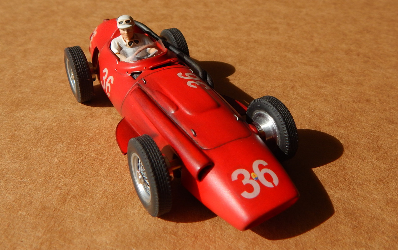 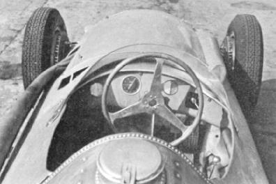 |
|
|
|
Post by richardh on Apr 17, 2020 13:35:40 GMT -5
Chris
Yes it is - but I realize the plan I posted for some reason the cockpit is mirrored. Nice photos of your car and the real thing - Thanks.
Richard
|
|
|
|
Post by pilot70 on Apr 17, 2020 16:40:21 GMT -5
Such a beautiful car!
And magnificient work and detail.
The idea behind the leaning Sir Stirling is a great tribute to the legendary driver and person that sadly left us last Sunday.
Congratulations for your fantastic model car.
Dan.
|
|
|
|
Post by predator on Jun 5, 2020 13:16:32 GMT -5
Hi Richard, Beautiful car, very beautiful car. I think that the wheels nuts are in the wrong way (left to right). 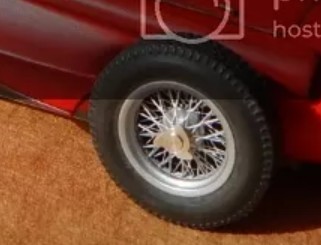 The pendulum driver is amazing and very well done. Thanks for sharing. Jean |
|
|
|
Post by richardh on Jun 7, 2020 10:49:46 GMT -5
Hi Jean
Thank you for your kind comments and especially the note about the wheel nuts the wrong way round. I appreciate the advice you experts in this Forum offer as there is always something new to learn - I will be fixing those and probably have them wrong on several other previous builds !
Regards
Richard
|
|


 DM
DM


