Post by Chris Wright on Jan 9, 2015 16:40:19 GMT -5
PART ONE
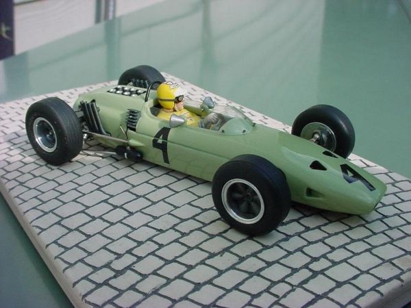
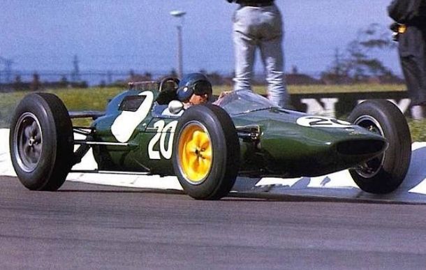
Lotus 25 R-3 has to been the mount for more drivers than any other Lotus 25 built. It has been driven by Jim Clark, Jack Brabham (photo below at the 1963 Monaco G.P.) Mike Spence, Pedro Rodriguez, Trevor Taylor (photo's below) Chris Amon, and Mike Hailwood.
Lotus 25 R-3 has to been the mount for more drivers than any other Lotus 25 built. It has been driven by Jim Clark, Jack Brabham (photo below at the 1963 Monaco G.P.) Mike Spence, Pedro Rodriguez, Trevor Taylor (photo's below) Chris Amon, and Mike Hailwood.
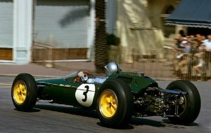
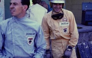
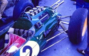
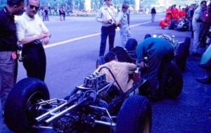
The subject of this build is Lotus 25, driven by Trevor Taylor at the 1963 Belgian GP. I found very few photo's of the car in the race, the ones I did find were the size of postage stamps. I did however find the four great photo's above. All from 1963, the first photo is Jack Brabham driving R-3 at the 1963 Monaco GP, unfortunately he retired on lap 77. The next 3 photo's are at the Belgian GP, they show show Trevor misbehaving, Colin getting mad at him, and a close-up of the engine cowl.
The base for this build is Mel Ault's new Pre-Wing body of the 1962 Lotus 25 R-2 as driven by Jim Clark at the British GP.
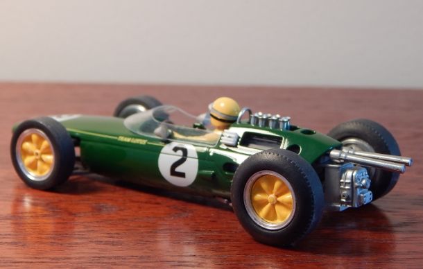
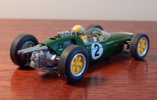
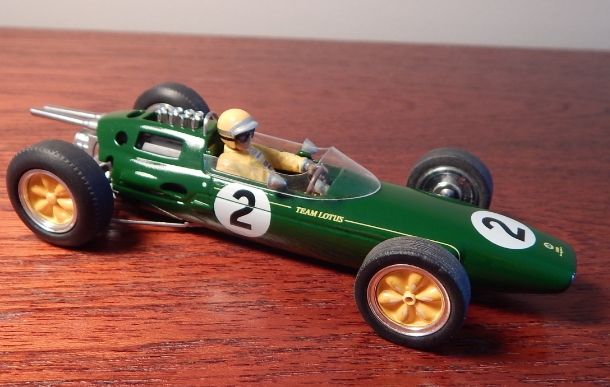
The subject of this build will be Trevor Taylor's R-3 as driven at the 1963 Belgian Grand Prix.
If you compare the above photograph of number 20, to the photo's at the beginning of the thread you can see, due to the updates Lotus made, the rear engine cowl has a few extra holes punched into it to accommodate a revised exhaust system, fuel injection and the relocation of the transistor ignition box.
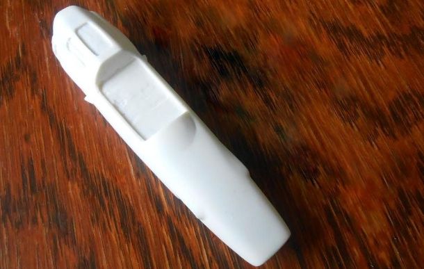
The Lotus 25 body as received from Mel, it also came with white metal exhaust, and rear view mirrors.
I did the usual things to the shell, all the holes were opened up, and the new apertures were positioned on the shell to replicate R-3 in 1963. The bottom edge of the body was also rework to accommodate the new Beardog MK3 chassis.
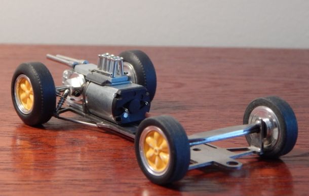
Next, chassis preparation. One of these days I'll have to do a tutorial on assembling a Beardog Chassis. It's tough though juggling a soldering iron, acid flux and a camera all at the same time.
This time instead of my usual Mashima motor, I decided to use the venerable 030 Mabuchi, why? because that's what most people will be using. As with all Lotus 25/33's space is very tight, and Mel had this body constructed to the correct dimensions, so it's small. Because of the tight confines under the engine cowl, I decided to mount the exhaust and motor details to the chassis via a 'L' shaped bracket that is attached to the motor mount plate. To this the exhausts are mounted via piano wire extensions. (the white metal exhausts were drilled out to accept the piano wire). Eight small diameter rods were mounted vertically on to a plastic plate for the bootlace ferule injectors, and partial cylinder heads, and coolant pipes were fabricated and also added to the plate. This detail can be seen through the cowl aperture.
The base for this build is Mel Ault's new Pre-Wing body of the 1962 Lotus 25 R-2 as driven by Jim Clark at the British GP.
The subject of this build will be Trevor Taylor's R-3 as driven at the 1963 Belgian Grand Prix.
If you compare the above photograph of number 20, to the photo's at the beginning of the thread you can see, due to the updates Lotus made, the rear engine cowl has a few extra holes punched into it to accommodate a revised exhaust system, fuel injection and the relocation of the transistor ignition box.
The Lotus 25 body as received from Mel, it also came with white metal exhaust, and rear view mirrors.
I did the usual things to the shell, all the holes were opened up, and the new apertures were positioned on the shell to replicate R-3 in 1963. The bottom edge of the body was also rework to accommodate the new Beardog MK3 chassis.
Next, chassis preparation. One of these days I'll have to do a tutorial on assembling a Beardog Chassis. It's tough though juggling a soldering iron, acid flux and a camera all at the same time.
This time instead of my usual Mashima motor, I decided to use the venerable 030 Mabuchi, why? because that's what most people will be using. As with all Lotus 25/33's space is very tight, and Mel had this body constructed to the correct dimensions, so it's small. Because of the tight confines under the engine cowl, I decided to mount the exhaust and motor details to the chassis via a 'L' shaped bracket that is attached to the motor mount plate. To this the exhausts are mounted via piano wire extensions. (the white metal exhausts were drilled out to accept the piano wire). Eight small diameter rods were mounted vertically on to a plastic plate for the bootlace ferule injectors, and partial cylinder heads, and coolant pipes were fabricated and also added to the plate. This detail can be seen through the cowl aperture.
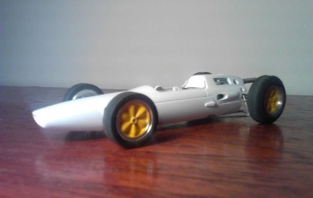
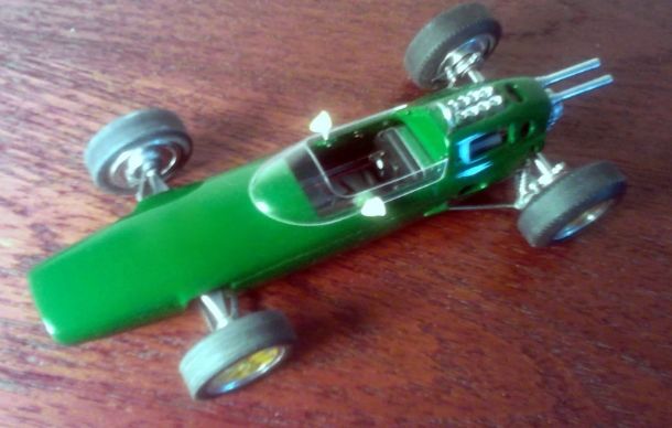
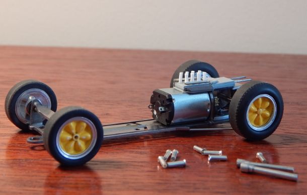
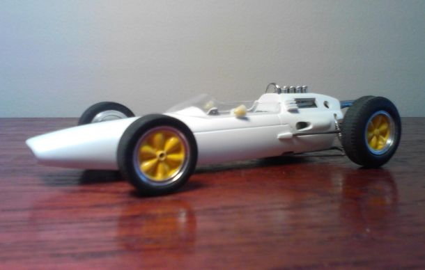
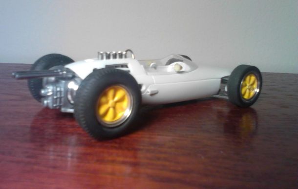
The body roughly mounted to the chassis! I like to get this done at this stage in the construction, and adjusted as early as possible. In this photo you can also see the start of the rear shock absorber assemblies. These are easy to install on the MK 3 chassis because of the small hole at the end of the chassis a-arms. The cockpit surround is fabricated with a tab either side for windshield retention held in place by the rear view mirrors.
The wheels are the last of my stock of BWA's with BWA inserts, painted Lotus yellow.
This is how a Beardog chassis comes.
You can just see the holes at the end of the a-arms, a fine piece of piano wire can be threaded from the protruding triangular attachment points on the sides of the chassis, to the holes in the a-arms, and up at a 30 degree angle.
Attach the shock to this angled extension of the wire, using aluminium tubes, and you favorite bic lighter spring.
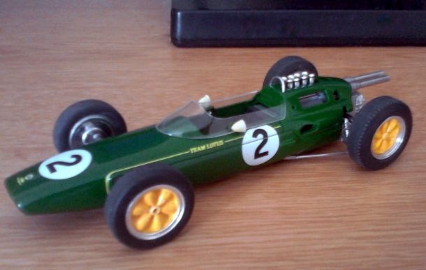
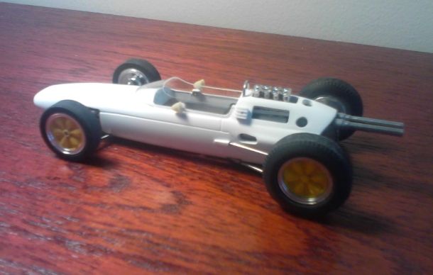
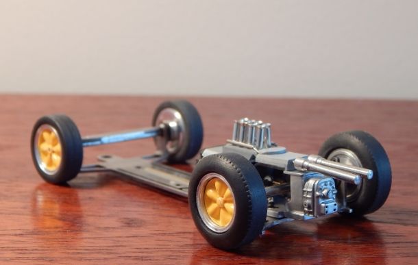
In this photograph you can clearly see, the installed shock absorbers, injection trumpets, drive gear and Exhausts. The dummy engine details have yet to be painted, and the little details like cam cover decals and exhaust blueing will be done at a later date, when the weather gets a lot warmer.
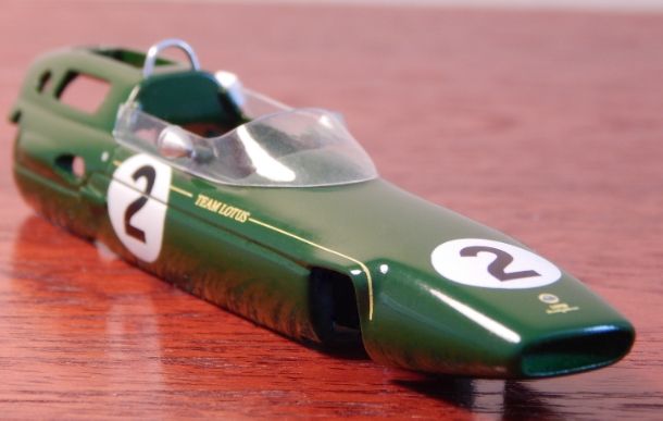
Windshield fitting time! I know nearly everybody leaves this step to last, why?...because the hate it, that's why I do mine now. Trim out the windshield bottom edge first until it fits the contour of the surround exactly. Fit it in place and hold it there with small pieces of clear tape. Using a very fine drill and a pin-vice drill a small hole (the size of a pin) through the clear windshield, and into the tab on the previously installed screen surround. Insert a pin. Do the same thing to the other side. Shorten the pin to about 1/4" long, mount the rear view mirrors onto the end of the pin. Now cut out the top of the winshield, and you're done...well that's the way I do it any way.
Note the installation of the transistor box, made up from layers of plasticard cut to size after glueing, and the roll bar made from the usual paperclip. Now I "site the car", I get out all the photographs that I can find, and mercilessly compare the car to the photo's, I tweak until I think it's as good as it's going to get, then leave alone.
At this stage I also insert the upper radius rods for the rear suspension, these are made up of thin piano wire, inserted in stainless steel tubing from RB Motion. One end fits in the body, the other in a small hole provided in the chassis rear upright. Whats missing? The dummy transmission, not my favorite thing to construct, pictures are up next.
Shots of both sides of the transmission. My version of a ZF box, made from scraps in my old plastic kit box. I shape it around the gear as much as I can, so that it gets hidden. The gear selector and rod has been fabricated, but will not be installed until the gear box has been painted black, with dull silver highlights to simulate exterior wear. You can see how tight everything is, there's not much room in there for a gear, so I used the last of mt Sonic/Beardog gears, but one of the great gears from Steve at Ranch Designs would fit too.
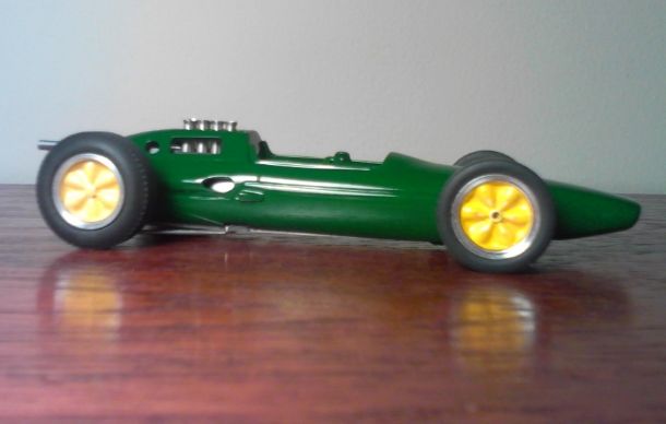
Paint! The part where everybody holds their breath. I first make sure the primer is flawless. I use Tamiya Fine White every time. If you heat the can you can get several coats on sanding between coats without excessive build-up. Then I wash and scrub with a soft tooth brush, and let air dry in a sealed box overnight. Next mount the body to a handle, like an old fine paintbrush handle inserted in the body mount screw hole. Heat the can of top-coat in very warm water in this case Tamiya Racing Green. Hold breath, I give it two light mist coats, followed by three heavy wet coats (30 minutes between coats of paint). Then put away in a dust-free environment. After 3 days, take out and breath again. If I find hichies I sand out with a Squadron Polishing stick, then polish the whole body with Tamiya polishing compound, then wash well with warm soapy water. Now I'm ready for Indycals New Lotus 25/33 decals.
MORE TO COME