

Post by Andrew Rowland on Jan 17, 2016 8:57:12 GMT -5
The Renault RS10 has been made by SRC quite differently to the Ferrari 312T4. This was done to accommodate the full height sides of the nose as well as incorporate the front wing and suspension elements.
This means that both taking the model apart to reuse the necessary parts and reassembly with the new telaio are slightly more complex.
Most of you should be able to do this without any problem and with basic modelling skills. Normal slot racers who do things like fettle their cars and replace the interiors with lightweight versions should also have no problems.
The only other thing to note before we start is that this conversion will require small areas of the donor body to be cut away and other parts like the front wing to be fixed in so that reassembly of the original car would require a reverse operation and some parts will be permanently changed.
Ok, onto the build.
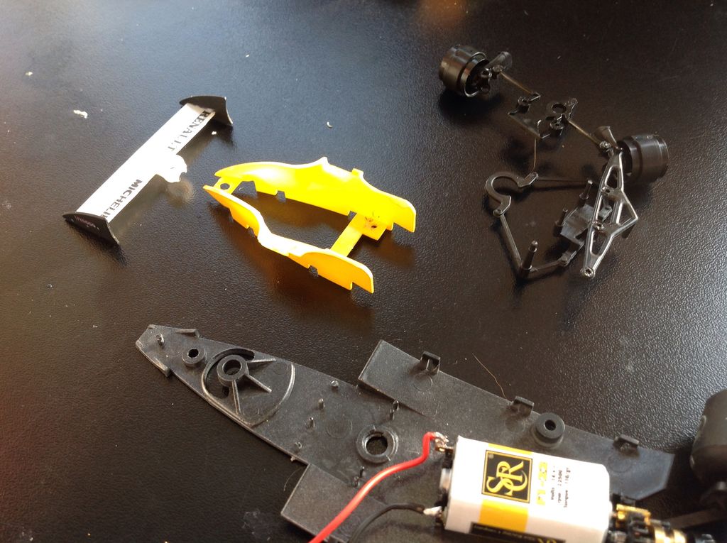
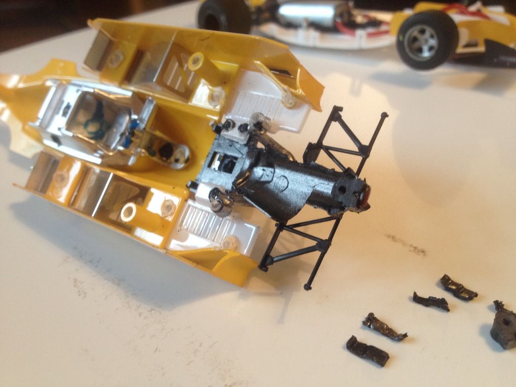
1. Disassembly.
1.1 remove the three body mounting screws and the rear wing mounting screw.
Set the screws apart for reuse.
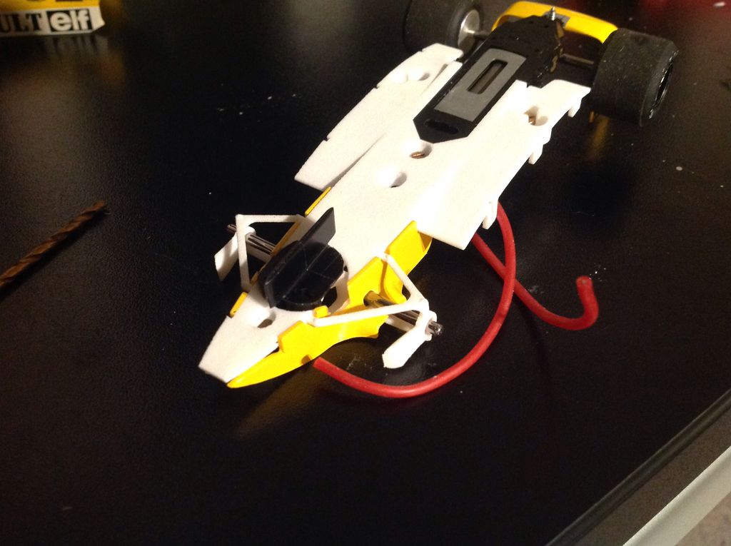
1.2 remove the guide then cut off the solder donut around the three mounting columns that hold the yellow nose cheeks (the yellow bit still fitted to the chassis) to the chassis.
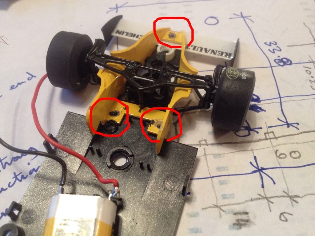
This will allow the cheeks and front suspension as well as the front wing to be pulled off the chassis.
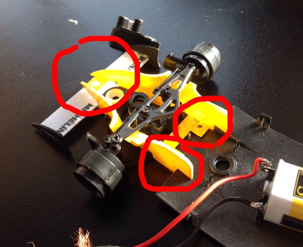
1.3 disassemble the front suspension web from the cheeks. You can do this destructively or by carefully opening one or two of the soldered joints. I did the latter just because I hate breaking anything....
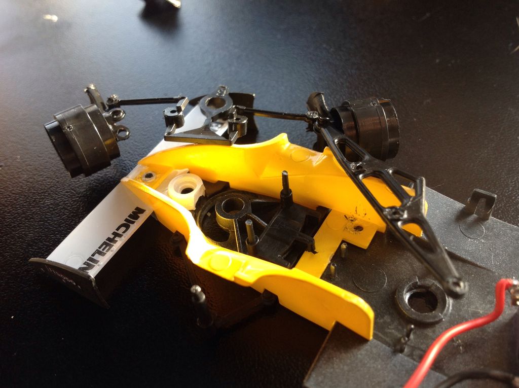
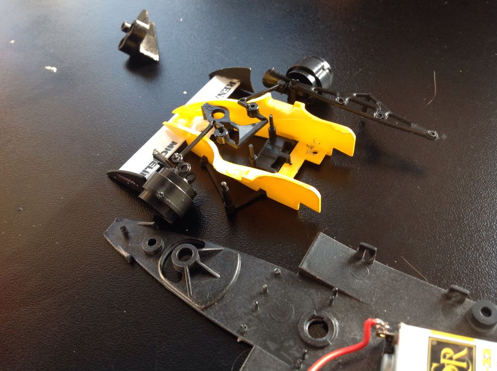
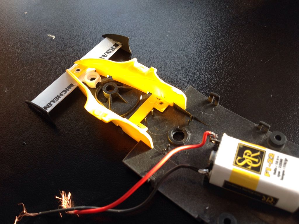
1.4 you now have the cheeks as a single piece and the front wing as another piece.
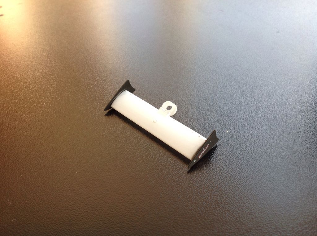
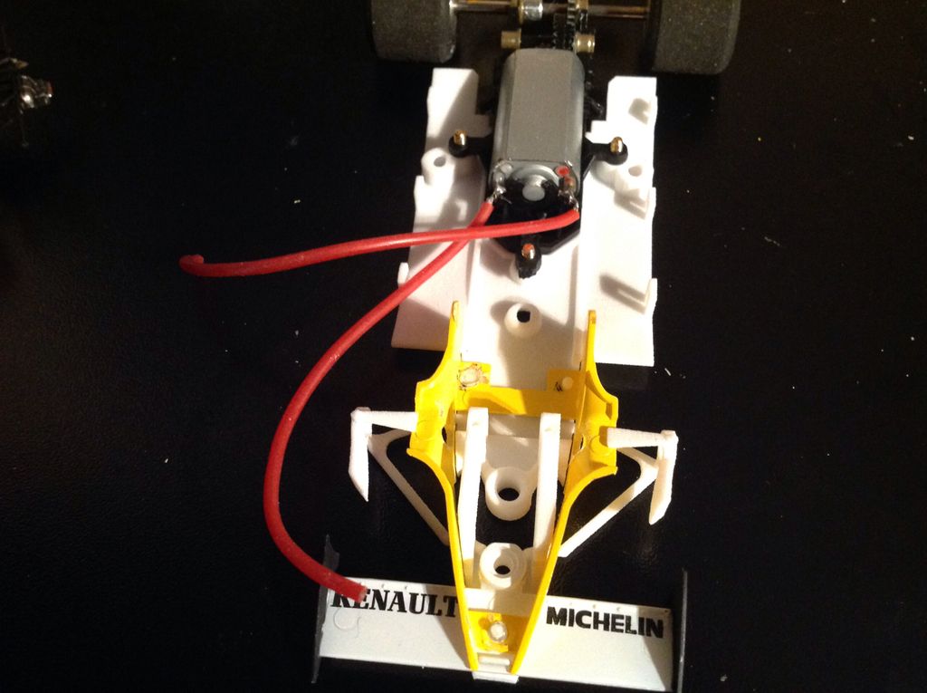
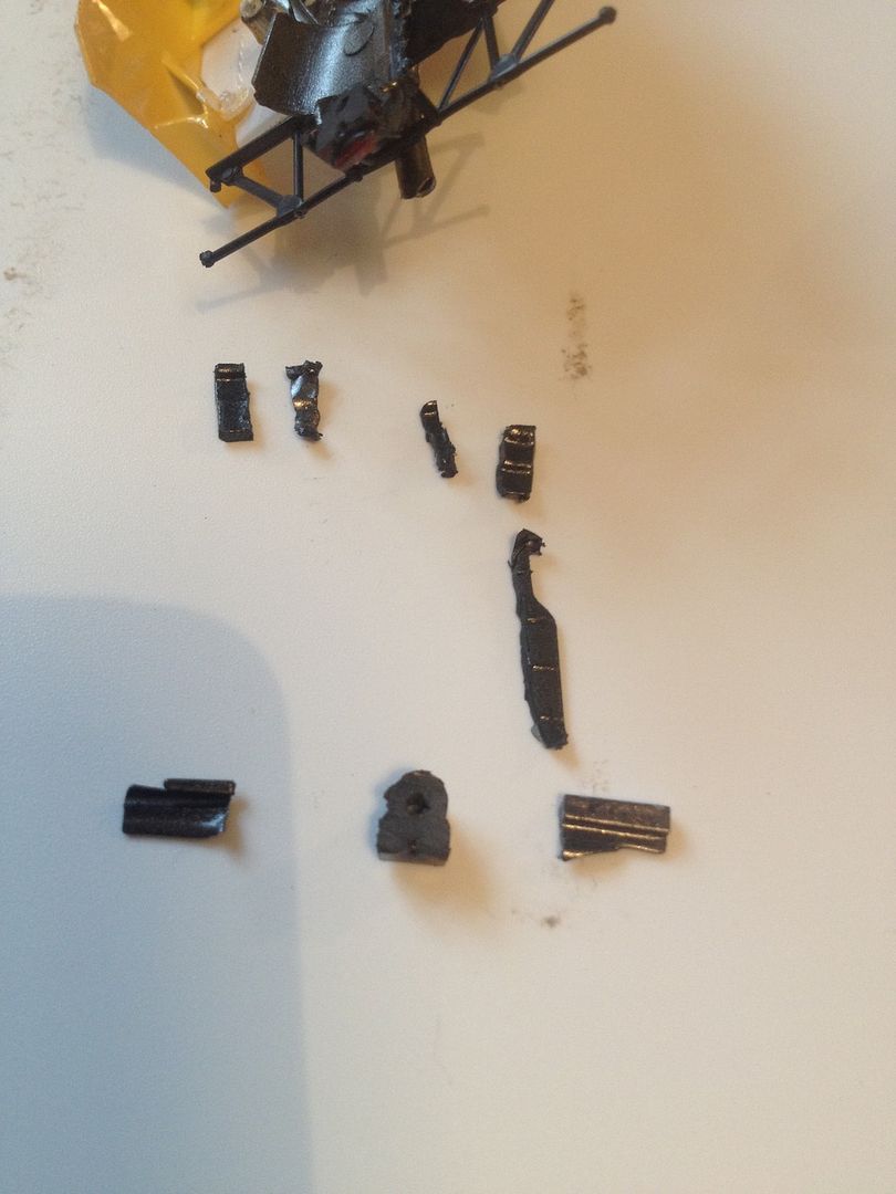
2. Rear Wing.
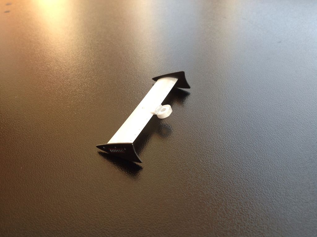
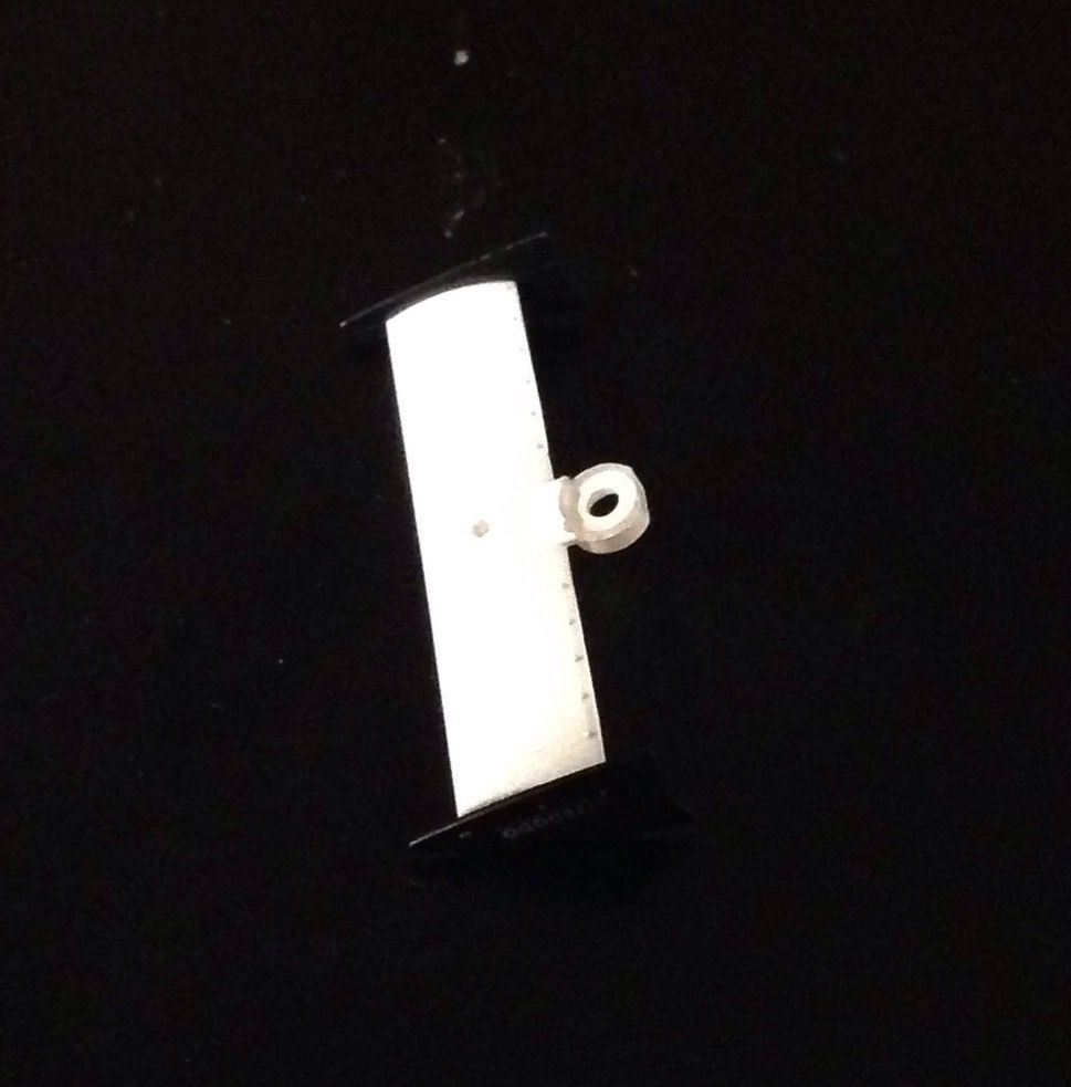
2.1 cut the front of the rear wing screw fixing plate off as shown. Try to accurately follow the cut I have made for best results.
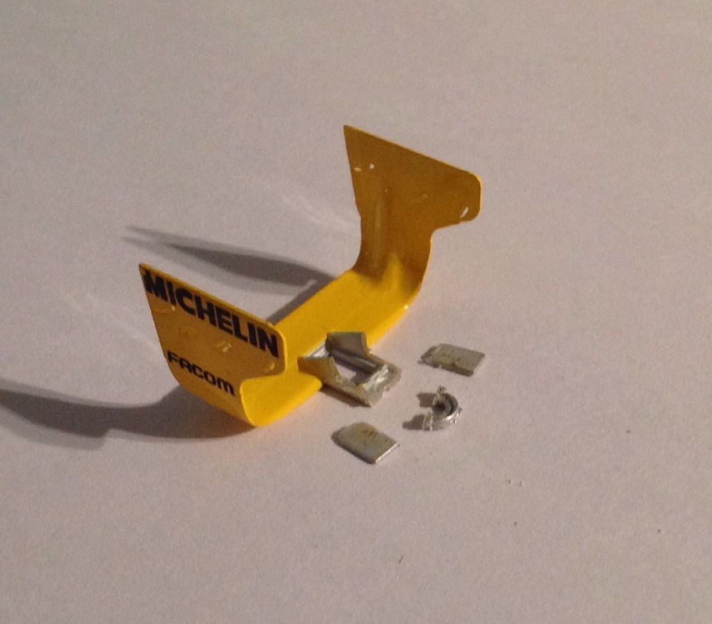
I made an error and cut off the sides. These should be left to add strength.
2.2 take one of the donor screws and screw the wing through the rectangular slot direct on top of the Policar gearbox. Don't screw too hard but it should hold very well.
2.3 one could look at cutting off the bottom of the self tapping screw or adding a small block of balsa or plastic to disguise the screw. Mine is left as is in the photos.
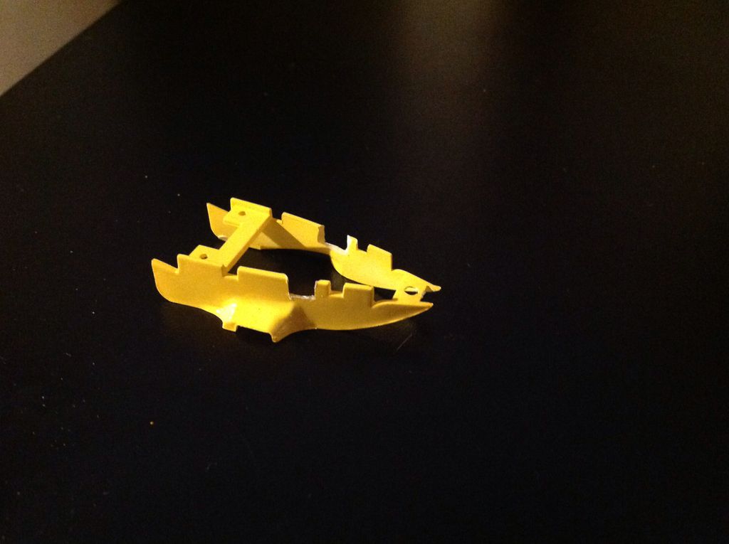
3. Front End.
I have redesigned the front end fixing to make it easier to assemble so the following is for those people who bought this chassis between 12/01/16 and 19/01/16. Those who have bought the new version will have a slightly easier assembly and should go to point 3.1.
3.0 the wing needs some adaptation to make it fit the new chassis. a) cut off the small section of the front wing fixing screw donut as shown in the photo and b) turn the wing over and remove the thin ring to let the wing sit flat on the new chassis.
You will also need to make some cuts on the chassis itself. When i first designed the chassis I used the standard Policar screw fixing system and as the 3D print has a minimum thickness I could not work out how to make the area thin enough. I have now worked out how to make the area work without the need to modify the underside of the wing and the front chassis. Apologies for the first buyers between the dates mentioned above who will receive the earlier chassis.
Essentially you need to cut off the forward part of the front screw fixing position. So it looks like this:
Dry fit this as you go to make sure that it seats properly before moving on.
Finally you will need to trim the circular upstand around the front of the guide hole so that the wing screw fixing firs flat on the chassis screw mount.
This all sounds complex but in practice should take a few minutes with scalpel or dremmel.
3.1 For the rest of you who receive the later version you will only need to cut the tiny flat part off the rear of the wing mount so that it does not foul the guide.
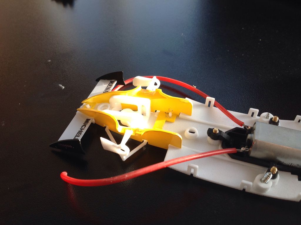
3.2 next start by offering up the front wing and cheeks. The top suspension arms will need to be bent outwards to get the whole thing fitted. Do this bending outwards slowly and from both sides so as not to excessively bend one side.
Note that the prototype in the photos lacks the seating areas on the inner ends of the top suspension arms. You chassis have these and this will make final fixing much stronger.
3.3 once seated the three little pillars on the chassis base will stick up through the cheek base and front wing.
3.4 now you need to cut small slots out of the lower sides of the cheek so that the guide can rotate fully. Fix the guide to the chassis and once again fit the cheeks. Rotate the guide back and forth to see how much needs to be cut out.
3.5 do not solder or glue yet because first you need to make the front axle holes. First take a long pointed thing (I used a cylindrical needle file) and poke it through the wheel hubs to mark the side of the cheeks where the axle needs to go through. Try to get this as accurate as possible.
3.6 you have two choices. Drill through with everything assembled and risk that the drill will slip on the non flat surface of the cheek or, disassemble and where you have marked drill through.
I suggest disassembly first. I also suggest use of a small pilot drill around 1mm dia......
.....Prior to the final drill of say 2.5 or 3mm diameter.
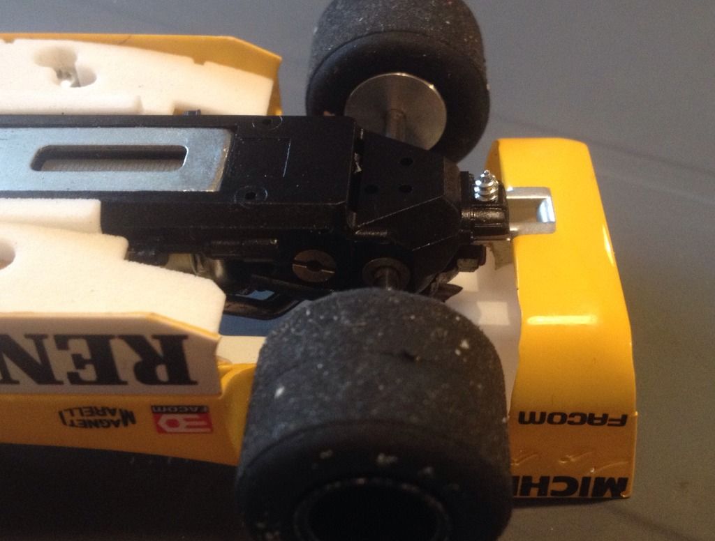
This is the final piece with hole and guide slot cut out:
Underside:
With axle in place.
3.7 one should check that the lumps on the ends of the upper suspension arms fit snuggly into the space left for them. Dry fit the top body too if necessary. Some very minor filing or cutting might be necessary. This might most easily be done to the cheeks or top body than risk breaking off the fragile suspension arms.
3.8 fit the whole thing together and use a soldering iron to melt the pillars on.
3.9 use glue or soldering iron to also securely fix the top suspension lumps in place. The idea of these is that they support end stress on the wheels so stopping them from moving inwards is the key.
Due to material dimensional instability it might also be necessary to cut a tiny slither off the front of the chassis so that when the top body fits down it does not hit it.
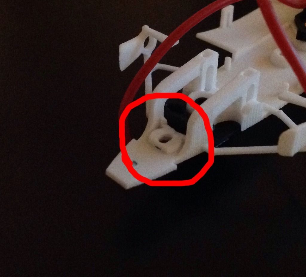
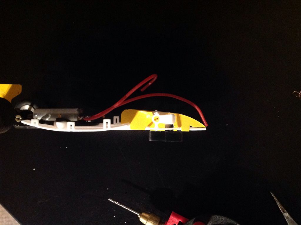
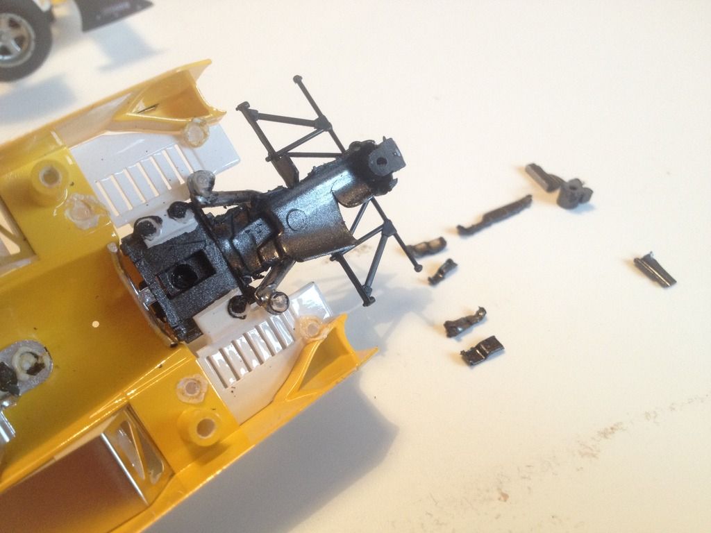
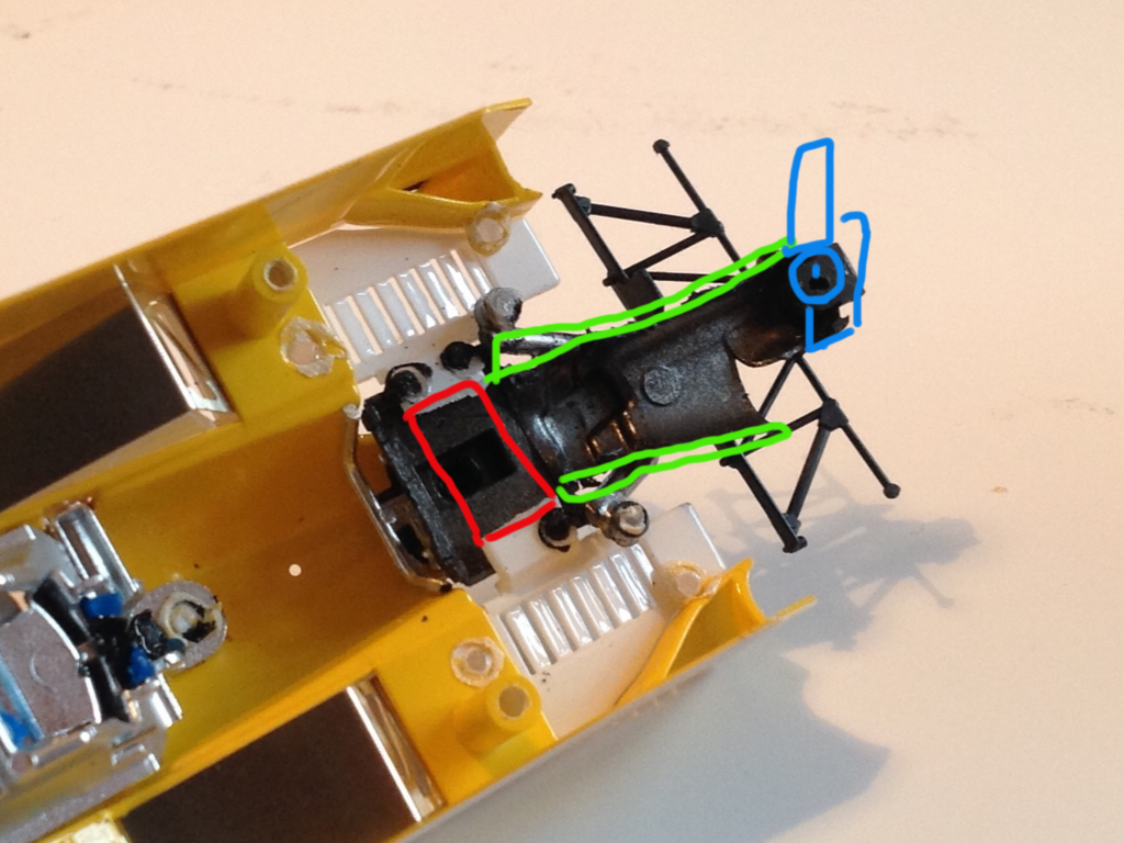
4. Gearbox
4.1 sufficient of the gearbox needs to be cut out to allow the motor and gearbox to sit up into the body. Rather more of this area needs to be removed than in the case of the Ferrari.
4.2 i have marked up the photos to show what has been removed. This is fairly delicate and disassembly of the various components might be preferable for some people.
4.3 once sufficient is cut out the chassis and body will fit so that all screw holes fit loosely onto their corresponding pillars without any pressure.
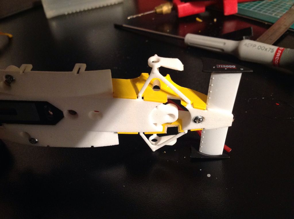
5. Final assembly
Fit the guide, skirts if you desire, wires and then screw everything together.

Congratulate yourself and go and race!
Cheers
Andi
This means that both taking the model apart to reuse the necessary parts and reassembly with the new telaio are slightly more complex.
Most of you should be able to do this without any problem and with basic modelling skills. Normal slot racers who do things like fettle their cars and replace the interiors with lightweight versions should also have no problems.
The only other thing to note before we start is that this conversion will require small areas of the donor body to be cut away and other parts like the front wing to be fixed in so that reassembly of the original car would require a reverse operation and some parts will be permanently changed.
Ok, onto the build.
1. Disassembly.
1.1 remove the three body mounting screws and the rear wing mounting screw.
Set the screws apart for reuse.
1.2 remove the guide then cut off the solder donut around the three mounting columns that hold the yellow nose cheeks (the yellow bit still fitted to the chassis) to the chassis.

This will allow the cheeks and front suspension as well as the front wing to be pulled off the chassis.

1.3 disassemble the front suspension web from the cheeks. You can do this destructively or by carefully opening one or two of the soldered joints. I did the latter just because I hate breaking anything....


1.4 you now have the cheeks as a single piece and the front wing as another piece.


2. Rear Wing.
2.1 cut the front of the rear wing screw fixing plate off as shown. Try to accurately follow the cut I have made for best results.

I made an error and cut off the sides. These should be left to add strength.
2.2 take one of the donor screws and screw the wing through the rectangular slot direct on top of the Policar gearbox. Don't screw too hard but it should hold very well.
2.3 one could look at cutting off the bottom of the self tapping screw or adding a small block of balsa or plastic to disguise the screw. Mine is left as is in the photos.

3. Front End.
I have redesigned the front end fixing to make it easier to assemble so the following is for those people who bought this chassis between 12/01/16 and 19/01/16. Those who have bought the new version will have a slightly easier assembly and should go to point 3.1.
3.0 the wing needs some adaptation to make it fit the new chassis. a) cut off the small section of the front wing fixing screw donut as shown in the photo and b) turn the wing over and remove the thin ring to let the wing sit flat on the new chassis.


You will also need to make some cuts on the chassis itself. When i first designed the chassis I used the standard Policar screw fixing system and as the 3D print has a minimum thickness I could not work out how to make the area thin enough. I have now worked out how to make the area work without the need to modify the underside of the wing and the front chassis. Apologies for the first buyers between the dates mentioned above who will receive the earlier chassis.
Essentially you need to cut off the forward part of the front screw fixing position. So it looks like this:

Dry fit this as you go to make sure that it seats properly before moving on.

Finally you will need to trim the circular upstand around the front of the guide hole so that the wing screw fixing firs flat on the chassis screw mount.
This all sounds complex but in practice should take a few minutes with scalpel or dremmel.
3.1 For the rest of you who receive the later version you will only need to cut the tiny flat part off the rear of the wing mount so that it does not foul the guide.

3.2 next start by offering up the front wing and cheeks. The top suspension arms will need to be bent outwards to get the whole thing fitted. Do this bending outwards slowly and from both sides so as not to excessively bend one side.
Note that the prototype in the photos lacks the seating areas on the inner ends of the top suspension arms. You chassis have these and this will make final fixing much stronger.
3.3 once seated the three little pillars on the chassis base will stick up through the cheek base and front wing.
3.4 now you need to cut small slots out of the lower sides of the cheek so that the guide can rotate fully. Fix the guide to the chassis and once again fit the cheeks. Rotate the guide back and forth to see how much needs to be cut out.

3.5 do not solder or glue yet because first you need to make the front axle holes. First take a long pointed thing (I used a cylindrical needle file) and poke it through the wheel hubs to mark the side of the cheeks where the axle needs to go through. Try to get this as accurate as possible.

3.6 you have two choices. Drill through with everything assembled and risk that the drill will slip on the non flat surface of the cheek or, disassemble and where you have marked drill through.
I suggest disassembly first. I also suggest use of a small pilot drill around 1mm dia......
.....Prior to the final drill of say 2.5 or 3mm diameter.
This is the final piece with hole and guide slot cut out:

Underside:
With axle in place.

3.7 one should check that the lumps on the ends of the upper suspension arms fit snuggly into the space left for them. Dry fit the top body too if necessary. Some very minor filing or cutting might be necessary. This might most easily be done to the cheeks or top body than risk breaking off the fragile suspension arms.
3.8 fit the whole thing together and use a soldering iron to melt the pillars on.
3.9 use glue or soldering iron to also securely fix the top suspension lumps in place. The idea of these is that they support end stress on the wheels so stopping them from moving inwards is the key.
Due to material dimensional instability it might also be necessary to cut a tiny slither off the front of the chassis so that when the top body fits down it does not hit it.
4. Gearbox
4.1 sufficient of the gearbox needs to be cut out to allow the motor and gearbox to sit up into the body. Rather more of this area needs to be removed than in the case of the Ferrari.
4.2 i have marked up the photos to show what has been removed. This is fairly delicate and disassembly of the various components might be preferable for some people.
4.3 once sufficient is cut out the chassis and body will fit so that all screw holes fit loosely onto their corresponding pillars without any pressure.


5. Final assembly
Fit the guide, skirts if you desire, wires and then screw everything together.

Congratulate yourself and go and race!
Cheers
Andi