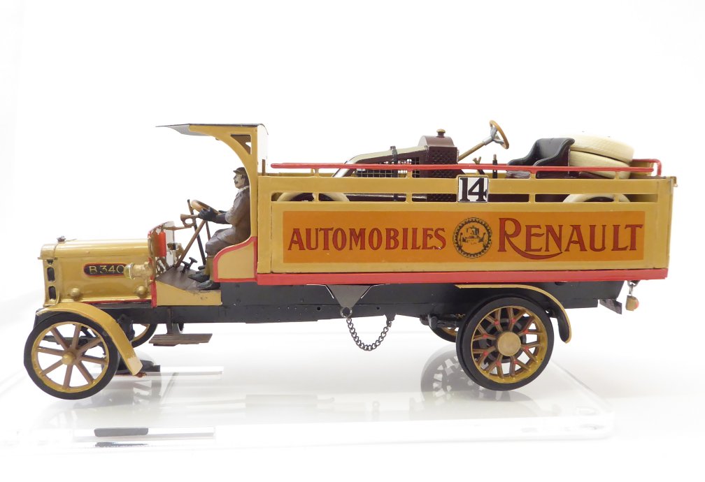
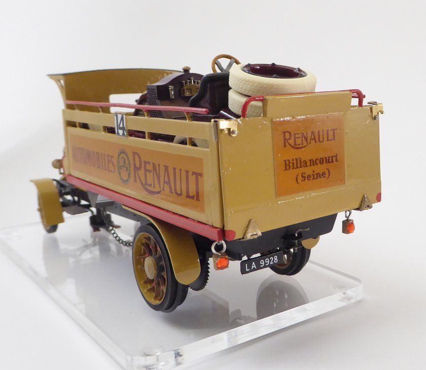
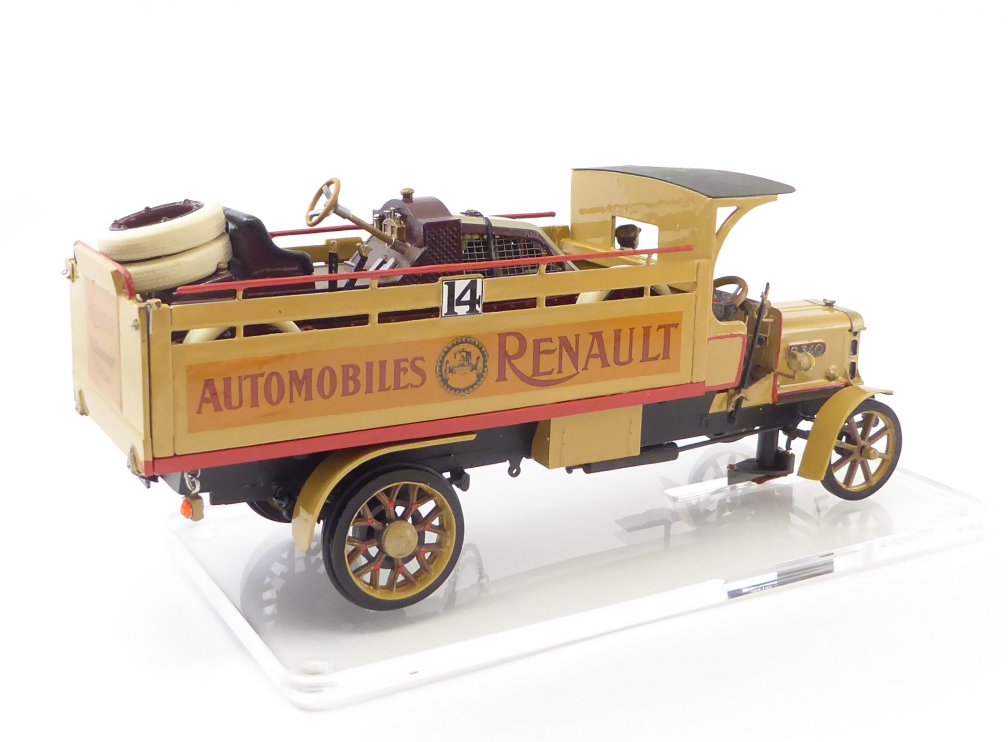
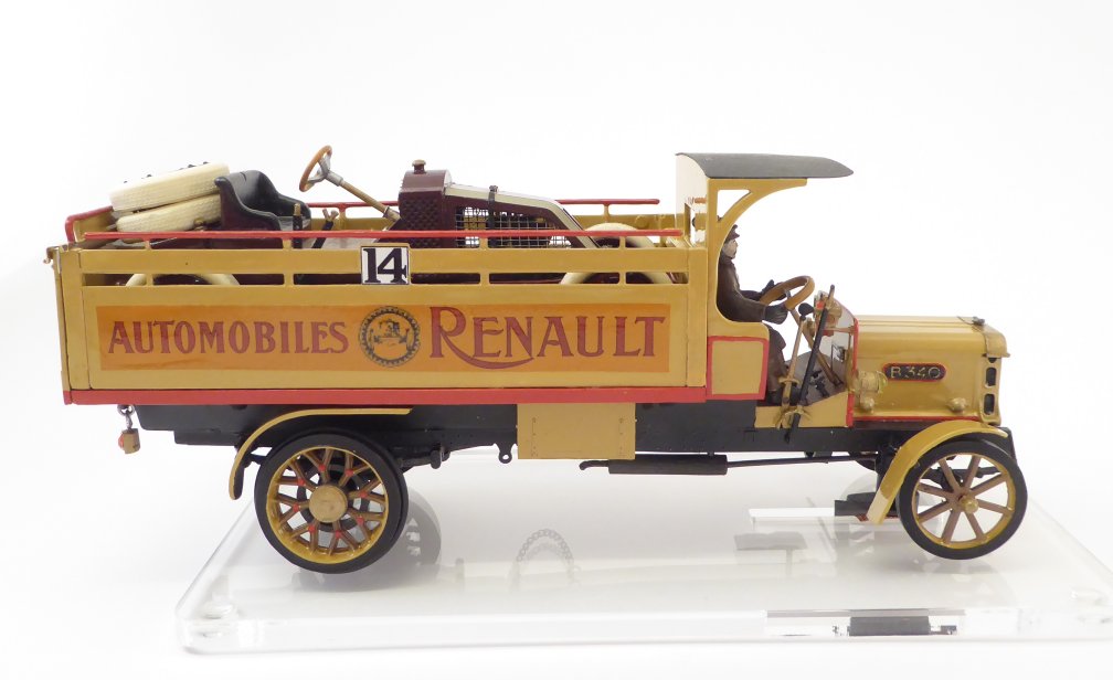
A slightly different slotcar - racing transporter 1910
Feb 26, 2021 12:15:26 GMT -5
WoodSlot likes this
Post by Taffy on Feb 26, 2021 12:15:26 GMT -5
Note: This is a longer, detailed construction report for the patient reader.
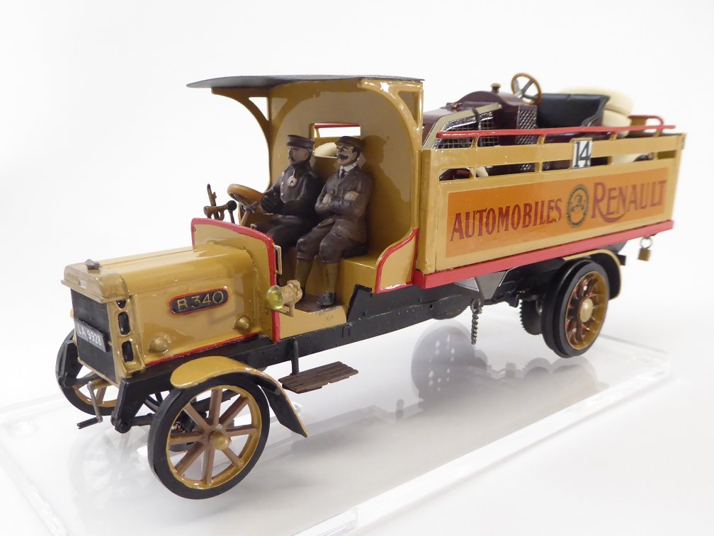
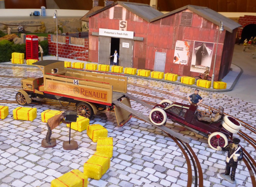
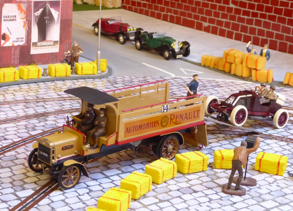
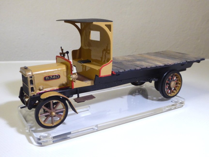
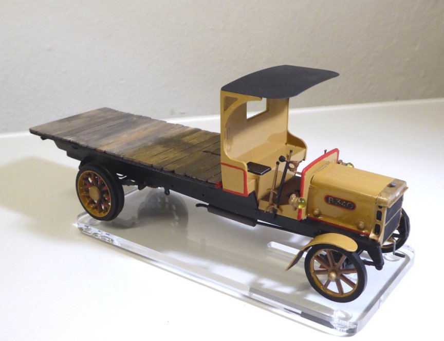
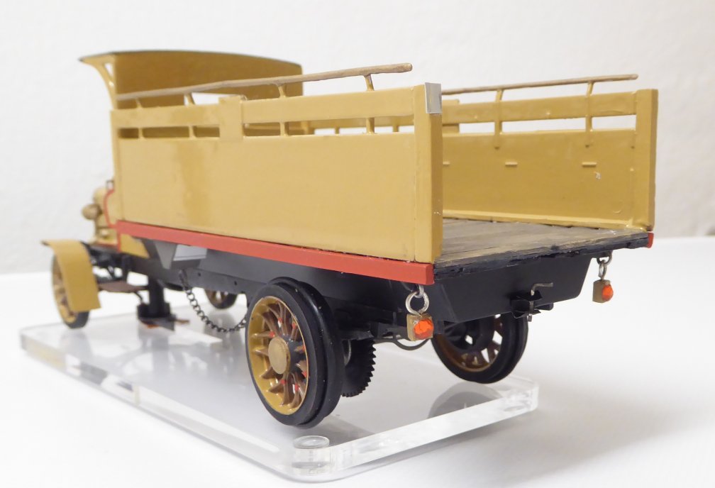
If you are only interested in the photos of the finished car, feel free to simply scroll down
So let´s begin!
While browsing through pictures, I happened to find a picture of a very early racing truck at PINTEREST
![]()

It's an American MACK truck, I suspect it was made in the early 1920s.
Lo and behold, the idea of moving racing cars from place to place by truck is not entirely new.
And suddenly, there was the question... how do my Edwardian Renault get to the racetrack?
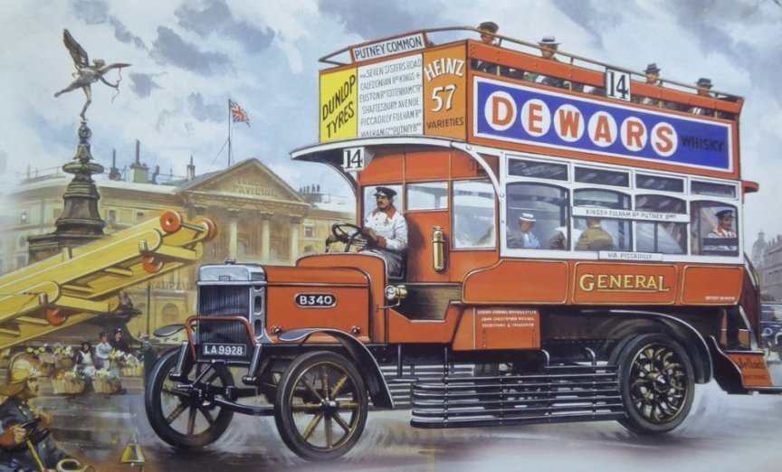
The next thing that happened was, that a slot colleague built the 1910 London Bus, a 1:32 scale kit from Airfix, motorised for the slottrack. What an idea!
![]()
It should be possible to make something out of it!
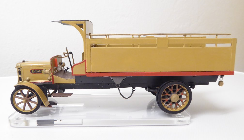
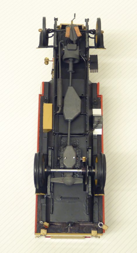
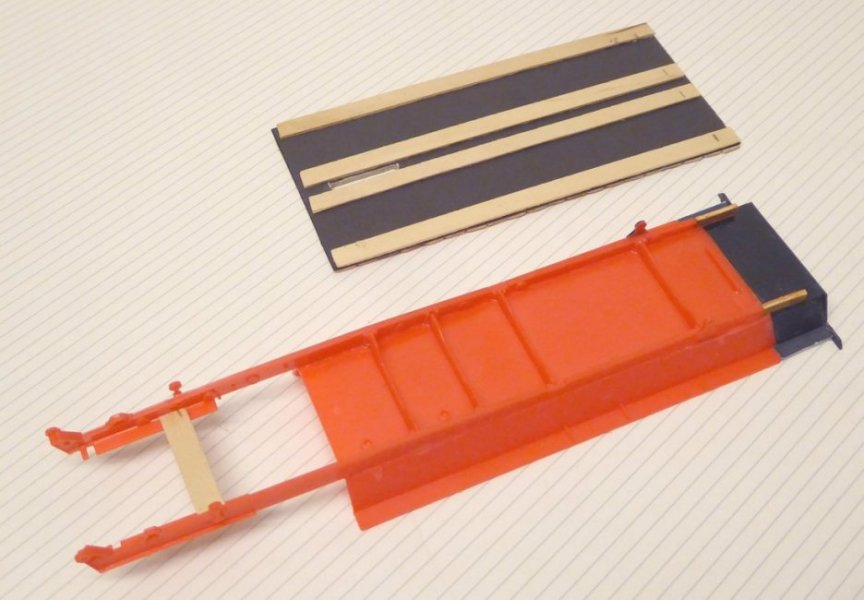
First I found out that the bus is too short for the required length of the loading area. So after I had glued the three essential frame components together, I first had to extend the frame.
Then I made a sandwich-style loading platform out of black cardboard and coffee stirrers.
![]()
The topmost layer of wooden sticks crossways, with the cardboard underneath and a few wooden sticks lengthways below it, results in a stable loading area.
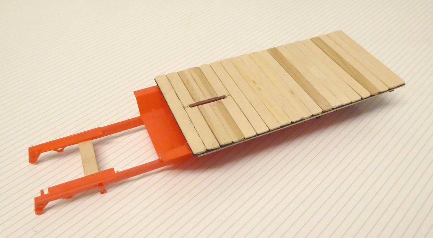
This seems to fit!
![]()
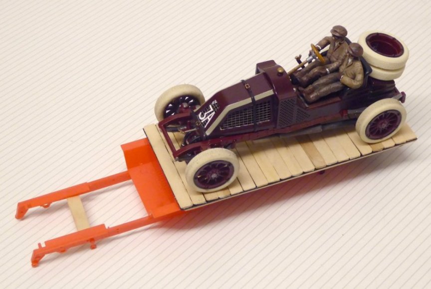
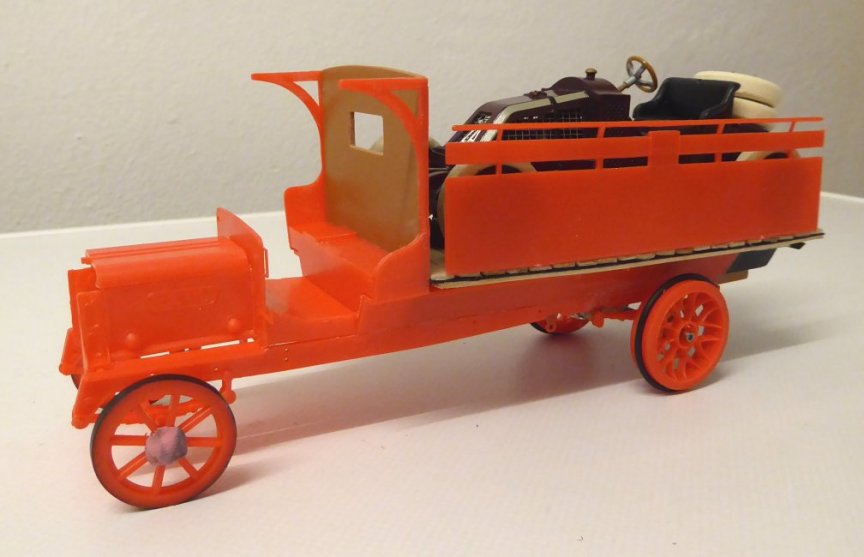
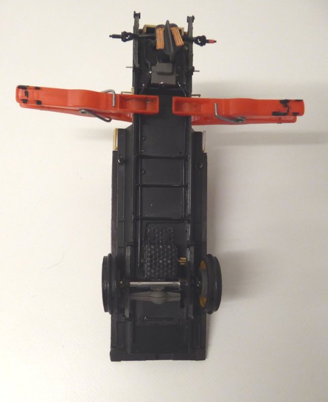
Of course, the wheelbase had to be adapted to the greater length by moving the rear axle mounts to the rear, but this was not a problem. Since the transporter is only intended for show rides and not for racing, I dared to use the relatively weakly dimensioned kit parts unchanged.
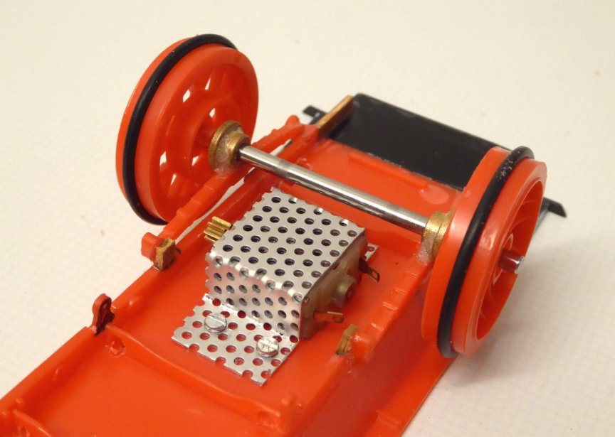
I glued two bearings to the springs of the rear axle with superglue and baking powder and adapted the rear wheels to a 3mm axle.
At the rear, the transporter has “heavy” twin wheels that are made up of two parts in the kit. I glued these together in such a way that there was a gap between the two wheel tires, into which I could pull a narrow black rubber ring, so that the track gets some grip.
I also wanted to use the front kit wheels, because the main load is borne by the guide flag at the front, so that should also work with the kit parts.
![https://www.taffys-home.de/Edwardians/Renault_Renntransporter/1910_racetruck_06.jpg]()
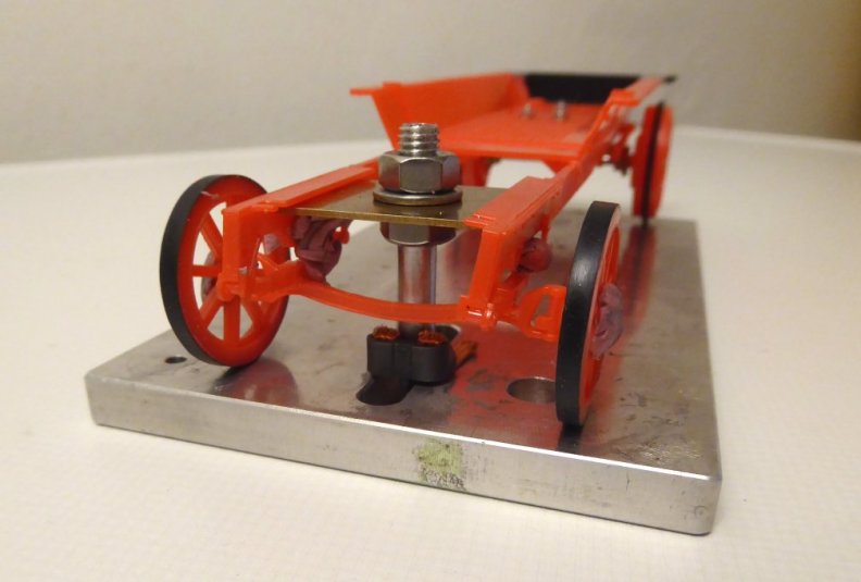
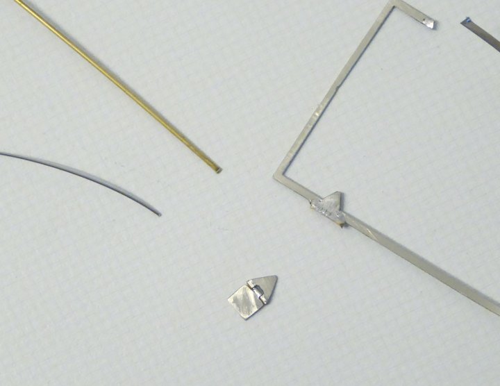
Then the guide: a brass plate that fits between the frame parts and holds the guideflag. I actually wanted to solder the corresponding tube to hold the flag, but no longer had a brass tube with a suitable diameter. But I had a suitable aluminum tube! Since it is currently not possible to just go to the hardware store here in Germany (because of the lockdown!), I tackled the aluminum pipe with the thread cutter and cut a thread with a lot of cursing and unsuccessful attempts so that I could screw the pipe to the brass plate.
![]()
If you are only interested in the photos of the finished car, feel free to simply scroll down
Second note: I apologize in advance for any errors in the text because I have used the Google translator.
Third note: No, this is no open wheeled car. Yes, I asked the ADMIN to post this 

Fourth note: I have divided this post into several parts to avoid restrictions by the forum software.
So let´s begin!
While browsing through pictures, I happened to find a picture of a very early racing truck at PINTEREST
It's an American MACK truck, I suspect it was made in the early 1920s.
Lo and behold, the idea of moving racing cars from place to place by truck is not entirely new.
And suddenly, there was the question... how do my Edwardian Renault get to the racetrack?
The next thing that happened was, that a slot colleague built the 1910 London Bus, a 1:32 scale kit from Airfix, motorised for the slottrack. What an idea!
The bus in a double pack with an early fire brigade was found between my other kits, a bit dusty.
It should be possible to make something out of it!
First I found out that the bus is too short for the required length of the loading area. So after I had glued the three essential frame components together, I first had to extend the frame.
Then I made a sandwich-style loading platform out of black cardboard and coffee stirrers.
The topmost layer of wooden sticks crossways, with the cardboard underneath and a few wooden sticks lengthways below it, results in a stable loading area.
This seems to fit!
Of course, the wheelbase had to be adapted to the greater length by moving the rear axle mounts to the rear, but this was not a problem. Since the transporter is only intended for show rides and not for racing, I dared to use the relatively weakly dimensioned kit parts unchanged.
I glued two bearings to the springs of the rear axle with superglue and baking powder and adapted the rear wheels to a 3mm axle.
At the rear, the transporter has “heavy” twin wheels that are made up of two parts in the kit. I glued these together in such a way that there was a gap between the two wheel tires, into which I could pull a narrow black rubber ring, so that the track gets some grip.
I also wanted to use the front kit wheels, because the main load is borne by the guide flag at the front, so that should also work with the kit parts.
I covered the front wheels themselves with an thin black film, because paint would rub off over time and then the red plastic would come out again.
After I got there I started thinking about the drive. It should be a small HO motor, i.e. a bracket made of perforated aluminum sheet (for better cooling) and adapted to a 48-tooth pinion.
Then the guide: a brass plate that fits between the frame parts and holds the guideflag. I actually wanted to solder the corresponding tube to hold the flag, but no longer had a brass tube with a suitable diameter. But I had a suitable aluminum tube! Since it is currently not possible to just go to the hardware store here in Germany (because of the lockdown!), I tackled the aluminum pipe with the thread cutter and cut a thread with a lot of cursing and unsuccessful attempts so that I could screw the pipe to the brass plate.
End of part one
 Taffy
Taffy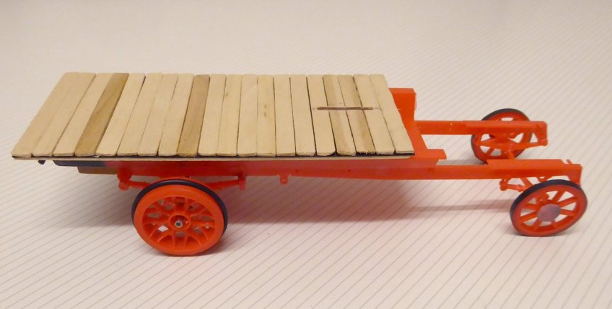
![https://www.taffys-home.de/Edwardians/Renault_Renntransporter/1910_racingtruck_21.jpghttps://www.taffys-home.de/Edwardians/Renault_Renntransporter/1910_racingtruck_21.jpg[/ img]](https://www.taffys-home.de/Edwardians/Renault_Renntransporter/1910_racingtruck_21.jpg)