|
|
Post by Chris Wright on Jun 6, 2012 12:17:05 GMT -5
Hi Russell, I've got bad news, and great news. First the bad news....I sold this car  Now the great news....I sold it to Andy Rowland, so we can expect this car to be magnificent when completed. ;D Chris |
|
|
|
Post by Chris Wright on Jun 6, 2012 12:18:34 GMT -5
Andy the pressures on, the Beardog's out of the bag.
Get to building
Chris
|
|
|
|
Post by Andrew Rowland on Jun 9, 2012 16:18:16 GMT -5
Hmmmm, yeah I guess one day i'll have to!
I did put a guide on and send it round our track. It needs quite a bit of work despite looking finished in the photos as Chris was mid changing it to a high exhaust version when he sold it to me....
Thanks for the pressure Chris - I was enjoying having a Beardog 'prototype' in my collection.
|
|
|
|
Post by Andrew Rowland on Jul 14, 2012 14:50:08 GMT -5
So Chris if I do have a go at this i'm gonna need some help!!
So as to try to go into your mind i'd like to understand a bit better where you were headed in order to make my decisions.
Instead of a pm i'm writing here so that hopefully others can benefit from the questions / answers....
Obviously it was a ling time ago you did this and a fair time since I received it but to start:
The chassis is sprung steel I believe;
a) how did you solder the suspension links on? Soft solder, silver solder or really welded? Can I use soft solder with a gas flame for sufficient heat?
As I said before I may want to modify the wheelbase and track and am considering how best to do this.
b) the chassis appears to have originally been thought as a 'flexible' member (there are thin cuts) but you then soldered a bar on the centre line which makes everything very solid.
I'm guessing this may have been a realisation that forward flex would create gear mesh / wear problems?
Actually the 4 wheels don't sit perfectly flat and i'd like to 'adjust' that or allow some flex to overcome varying track conditions. Maybe though the chassis 'gauge' is anyway too thick for that? Any comments would be welcome....
Finally for now.... The nose in the photos Russell published above is very like the photos of the real cars I see published with the inlet hole very horizontal and parallel. You must have later modified it as the nose I have is different - less parallel and less wide.
The question is simply whether this was intentional to copy an actual car or was it just an 'incomplete' work not yet looking quite right?
That's enough for now Chris - I hope you can help me make this into the car we both dream of......
|
|
|
|
Post by Chris Wright on Jul 15, 2012 13:04:14 GMT -5
Obviously it was a ling time ago you did this and a fair time since I received it but to start:
Yes Andi this car was built a long time ago. I originally started building the Lotus 63 for a proxy race to be held here in the States hosted by the Late Mr. Rocky Russo (Professor Fate).
That was 2005 or so because I was in full swing making Beardog Racing cars. The chassis on the Lotus is based on two Spring Steel McLaren M-16 indy car chassis. The wheelbase is 3 3/8” I believe. I did not set the wheelbase at exactly the scale requirement because the rules for this proxy event were a little less restrictive.
I never completed the car because I had to find full time employment, so that I could pay bills etc. and unfortunately the proxy race was a disaster because of Rocky's failing health. (His passing was a great loss to our hobby may I ad, he is missed)
The original car, as seen in Russell’s photographs was based very loosely on a Classic shell, and depicted the prototype in one of it’s many early variations with a high wing and low exhausts. The car was never sent to the Proxy Race and stayed in this state of completion for several more years.
The chassis is sprung steel I believe;
a) how did you solder the suspension links on? Soft solder, silver solder or really welded? Can I use soft solder with a gas flame for sufficient heat?
Yes the chassis is spring steel, and is soldered together with silver solder, and ample applications of acid flux (really important). I used an 80 watt soldering iron, but if you anchor the pieces down to your building board firmly you may be able to get away with using your torch.
As I said before I may want to modify the wheelbase and track and am considering how best to do this.
The wheelbase should be pretty close to accurate, because the chassis fit Charley Fitz’s body very well. The track may be easier to modify once modern wheels and tyres are chosen, I think NSR Wheels and tyres may work, with resin inserts made from scalex Lotus 49 wheels, neither of which were available when this model was conceived.
b) the chassis appears to have originally been thought as a 'flexible' member (there are thin cuts) but you then soldered a bar on the centre line which makes everything very solid.
Yes this chassis did have some flex, just like my latest chassis but this only works in a 2WD application like in the McLaren, and you're right any flexing of the front would cause the Aluminium Beardog Gear to strip immediately.
Actually the 4 wheels don't sit perfectly flat and i'd like to 'adjust' that or allow some flex to overcome varying track conditions. Maybe though the chassis 'gauge' is anyway too thick for that? Any comments would be welcome....
Twist the chassis with 2 pairs of pliers so that all the wheels touch, when you apply heat to this spring steel as in soldering, it sometimes can warp a little, or maybe my precision was a little off.
Finally for now.... The nose in the photos Russell published above is very like the photos of the real cars I see published with the inlet hole very horizontal and parallel. You must have later modified it as the nose I have is different - less parallel and less wide.
The question is simply whether this was intentional to copy an actual car or was it just an 'incomplete' work not yet looking quite right?
The original nose as in Russell’s photographs may have looked right, but it was not long enough. This became apparent when I considered painting and applying decals, there would not have been enough room to apply the number roundel and all the Lotus powered by Ford guff on the nose etc. I also made the body sides less slab sided and put the correct profile on them.
I also started converting it to the high exhaust version, sans wing because that's the car that Graham Hill tested, and hated.
I have loads of photo’s I can send, and will do so if you need them.
I like most members of this forum improve with age, my modeling skills are better, and my application is a lot more critical, it’s been quite some time since I built that car Andi, good luck, and I’m always available to help, but your skills are improving at an alarming rate. (remember you trepidation over the Gold Leaf colour scheme?) I'm sure you'll be able to complete the car to the envy of everyone.
Chris
|
|
|
|
Post by Andrew Rowland on Jul 16, 2012 10:14:37 GMT -5
Hey Chris thanks for your time - sorry if my questions seemed like I was putting you on the line so to speak.... Just for the record that was certainly not my intention - I was happy, as you know, when I received the car and remain so today. I am as you put it "trying to improve with age" and I also think that the 'scene' (at least the hard body scene) in which we are working has evolved over the last period to become a little more detail and 'scale' obsessed and so I just want to get things as right as is possible..... Frankly i'm STILL really scared of 3 colour paint schemes and although my Lotus 72 looks pretty good in a few grainy computer shots I could point out a few things that really I should have done better!! Only thing I want to pull you up on is calling the sponsors logos "guff"...... tut tut now, just 'cos I like cars dressed as cigarette packets and you don't...  OK, i've got some blueprints printed out and i'm gonna try this thing once and for all - wish me luck. |
|
|
|
Post by Chris Wright on Jul 16, 2012 10:24:27 GMT -5
Andi, I only just stopped smoking 6 months ago, so i'm only a little 1riTablE  By guff I meant the Lotus word , the Lotus logo and then the word Ford, and all this has to be over-laid on the gold colour curve. Oh by the way....Good Luck! |
|
|
|
Post by Andrew Rowland on Sept 12, 2012 0:39:49 GMT -5
So I’ve started making a little progress on this beast…. First, I stripped down the hole car and thought for some (a long) time! I think this car was devised pretty early on in Chris’s career and I felt it needed a little bit of refinement in the mechanical part. As it came to me the front drive shaft was attached to the motor with a presumably scratchbuilt copper ‘spring’ (seen in some shots above). The pinion end was held by a wedge shaped aluminium bush. The ‘point’ was that all this didn’t align particularly well and on the few laps I ran as a test the whole car virtually vibrated out if the slot….. The first thing I noticed was that the motor itself was pointing up in the air at the front. This would have been the result form the fact that the motor mount itself has been soldered on rotated backwards in order that it runs under the top wishbones. I simply filed down the motor mount working from the bottom until the motor sat parallel with the chassis and the front drive shaft sat perfectly central on the front bush hole…… 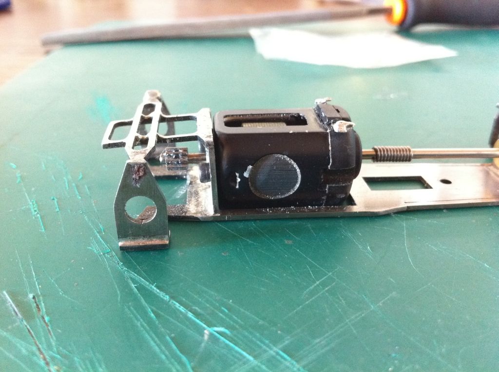 Which isn’t by the way actually central. That means that actually the car is very slightly set up as an ‘agnle-winder’! 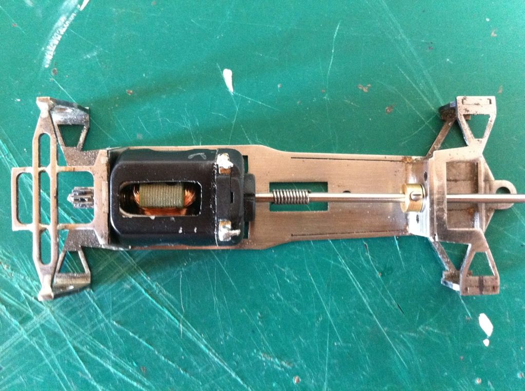 I also soon realized that the new drive shaft needed to be fixed to the motor with a similar flexible spring coupling otherwise the motor and drive shaft assembly would never be removable! 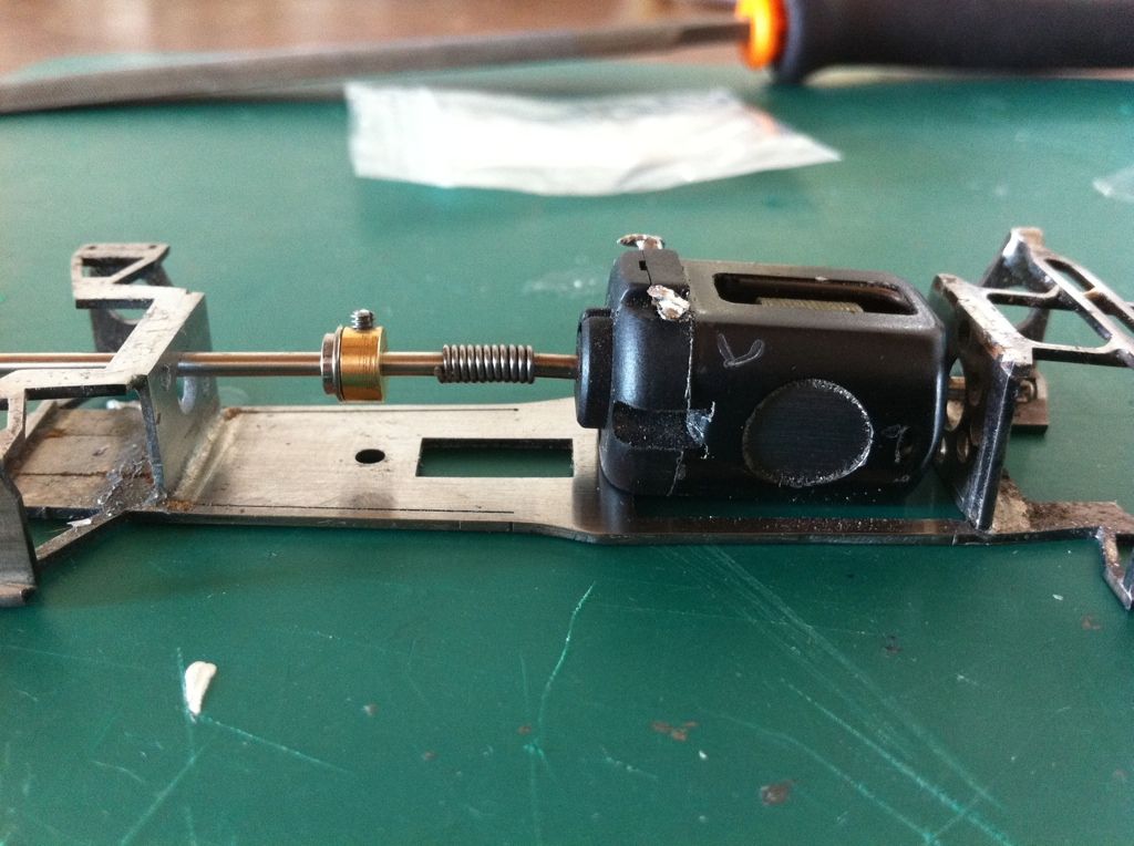 Then I assembled a 2mm drill blank, cut to length, added a ball race from SMB and a brass collar from ‘hobbys’ in the UK, linking it to the motor with a spring from an old Carerra Porsche used in the MMM. Here we see the shaft ready. 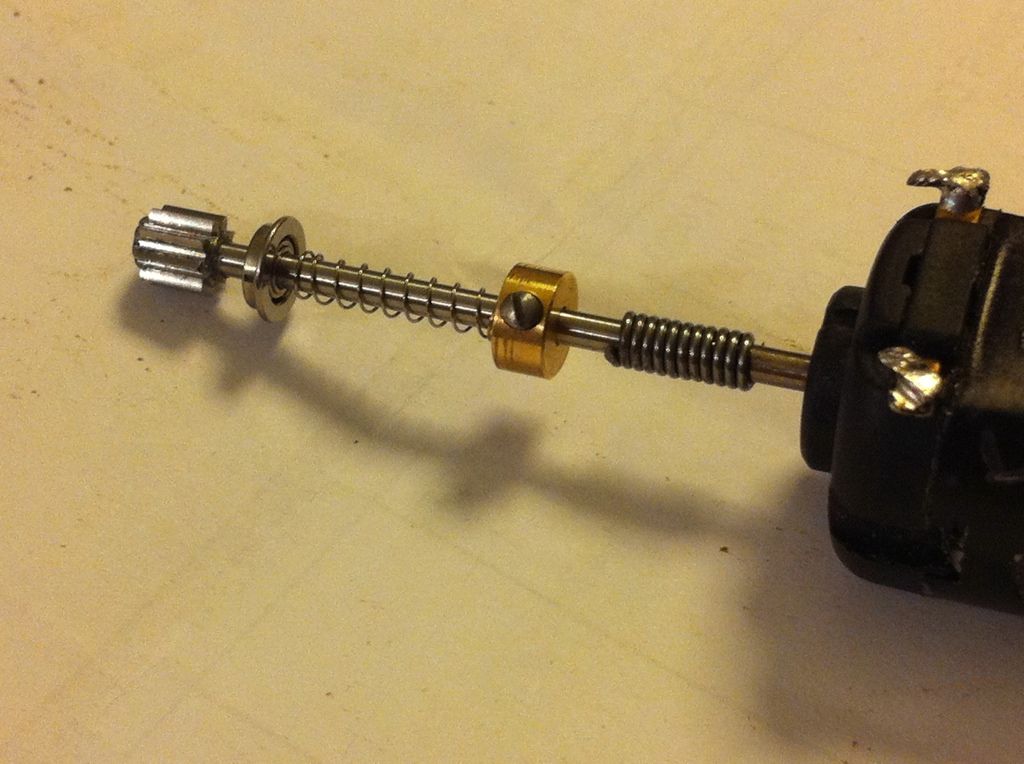 Although the chassis is a decent lump of steel stopping almost completely rotational flex, given that the zones either side of the motor are only about 1x1.5mm in section there is still quite a lot of bending flex in the chassis. I don’t believe this will cause mesh problems with the gears but it could cause problems with excessive friction between the front drive shaft and the ball race. I opted to leave the ball race ‘lose’ in its hole and moved the collar away from it with a spring in between. The idea here is to avoid a ‘fixed’ position for the collar hard up against the ball race to retain it and allow instead the force of the spring alone to hold the ball race in place. This seems to work in my dry fit and we will have to see whether the spring is strong enough to withstand a shock on track allowing the ball race to jump out…. The final assembly looks like this with a new 64pitch, 9t pinion (from AB slotsport) on the front to match the original 9t on the rear. Chris suggests that common wisdom suggests the fronts should be geared to turn quicker than the rears but as that seems odd to me I’m going to start with identical gearing and work from there…. I have 2x 7t and 2 x 8t pinions waiting testing too…. The other thing that I wanted to address was the wheelbase which was about 4-5mm too long. I have seriously modified the front top wishbone and upright assembly and this works but is currently rather weak. This will need further thought and refinement before any track time…. 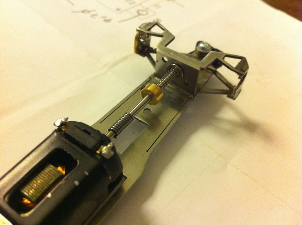 So the rolling chassis is taking shape. I’m having a hell of a time sourcing suitable tyres for this car. I seem to have found something useful from NSR so I just need to check them and then order. This was just made up using the 2 sets of rears from my Spanish Scaley original and repro Tyrrell 001/2 models from my collection since they seem to be about the only thing that comes close that I currently have. Oh the wheels are the original BWA numbers, I think made just for Chris for this car. They weigh a tonne so they’ll be replaced with NSR too….. 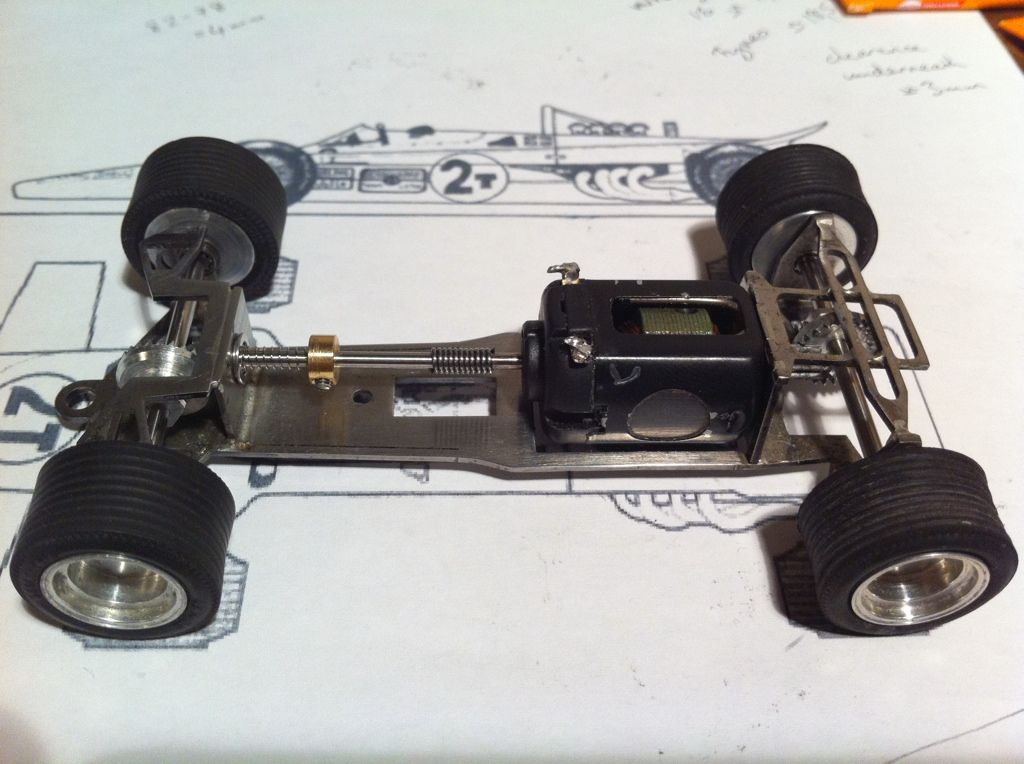 |
|
|
|
Post by Mark Huber on Sept 12, 2012 1:44:24 GMT -5
The story on this car (not the real one... this one) would (will?) make a brilliant article in SlotCarMag! I cannot wait to read Chris' comments... wow Andi, you've really polished and cut this diamond nicely. But.. BWA wheels... heavy? Cheers, |
|


